Fishfiles 20,145 Posted June 11, 2021 those ES's need a GOOD fully charged with reserve battery to function ---- seen many times in the woods where the ESs wouldn't shift , stuck in gear , head lights would work , but no shift , we connected battery cables to it as a jump , and they shifted fine as long as the cables were hooked up 1 Share this post Link to post Share on other sites
Bossdaddy 209 Posted June 11, 2021 I believe the battery is good. My charger had already cut back to trickle after about 30 mins. of charging. But you are right, I've heard lots of stories about batteries and the ES. Share this post Link to post Share on other sites
Bossdaddy 209 Posted June 11, 2021 Retro, thanks for the help today, I got to go to grandkids softball tournament shortly. If you have a list of test I can do just post them I'll be back at it tomorrow morning. Have a good afternoon and night. I trust you, I'm still lost. Share this post Link to post Share on other sites
retro 4,048 Posted June 11, 2021 Ok, the charging system voltages are within specifications so it is safe to continue testing. We have learned that the original ECM have failed since it does not supply voltage to the main relay coil through the Black/Orange wire. So we were right about that component being bad. The loaner ECM supplies voltage through the Black/Orange wire to the relay coil, but it still does not shift with the loaner plugged in, so we may have a 2nd issue to diagnose. We'll continue to look for the 2nd issue with the loaner plugged in... 44 minutes ago, Bossdaddy said: Retro, thanks for the help today, I got to go to grandkids softball tournament shortly. Ya thanks, we are having fun! I just had visitors arrive unexpectedly, sorry that I had to disappear on ya for a bit... Enjoy your grandkids softball game, I hope they win it!. I have to leave at 6:30 this evening so its all good that you have something fun to do this evening. 🙂 I'll be back later tonight with tests for tomorrow. Keep a smile on and have fun! 1 Share this post Link to post Share on other sites
retro 4,048 Posted June 12, 2021 Lets test the shift motor in circuit. You'll need two jumper wires that are long enough to reach the battery from the ECM. With the key off, unplug the 5p shift ECM connector from the loaner ECM. Poke one end of a jumper wire into the Orange wire terminal inside the 5p harness connector and attach the other end of that jumper wire to the positive battery terminal bolt. Poke one end of a 2nd jumper wire into the Green/Blue wire terminal inside the 5p harness connector and momentarily touch the other end of that jumper wire to the negative battery terminal. The shift motor should attempt to upshift each time you momentarily touch the negative battery terminal for about 1/3 of a second. Then swap locations of the two jumper wires that are poked into the ECM 5p harness connector. The jumper that was poked into the Orange wire terminal should now be poked into the Green/Blue wire terminal and the jumper that was poked into the Green/Blue wire should now be poked into the Orange wire terminal. Momentarily touch the negative battery terminal with the end of the 2nd jumper wire again. The shift motor should downshift each time you momentarily touch the negative battery terminal. Downshift until the transmission is back in Neutral. Does the shift motor operate in both directions? Share this post Link to post Share on other sites
retro 4,048 Posted June 12, 2021 Next lets test the shift switches in circuit with your test light and a jumper wire. With the key off and everything plugged in, unplug the 16p shift ECM connector. Poke one end of a jumper wire into the Black/Red wire terminal inside the 16p harness connector and attach the other end of that jumper wire to the positive battery terminal bolt. Connect your test light lead to the negative battery terminal. Probe the White/Blue wire terminal inside the 16p harness connector with your test light and depress the "UP" shift button on the handlebar. The test light should illuminate each time you depress the "UP" button. Then probe the White/Yellow wire terminal inside the 16p harness connector with your test light and depress the "DOWN" shift button on the handlebar. The test light should illuminate each time you depress the "DOWN" button. Share this post Link to post Share on other sites
retro 4,048 Posted June 12, 2021 Since the test light is seeing some action here and the 16p ECM connector is unplugged, lets quickly test the reverse lockout switch with it. Connect the test light lead to the positive battery terminal. Then probe the Gray/Red wire terminal inside the 16p harness connector with your test light. The test light should not illuminate. Now depress the reverse button on top of the left hand brake and pull the brake lever back to apply the rear brakes. The test light should illuminate while the left brake lever is pulled back. Share this post Link to post Share on other sites
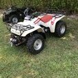
retro 4,048 Posted June 12, 2021 Next lets test the gear position switch with the test light in circuit with the shift ECM. With the key off and everything still plugged in except for the 16p ECM connector, unplug the Gear Position switch 4p connector. Refer to the picture below to find the Gear Position switch 4p connector clipped onto a steel tab on the right side-rear of the frame. Connect the test light lead to the positive battery terminal. With the transmission in Neutral probe the test light into the Light Green/Red wire terminal inside the ECM 16p harness connector. The test light should illuminate. Now probe the test light into the Gray, White/Green and the Light Blue wire terminals inside the ECM 16p harness connector. The test light should not illuminate while probing those three wire terminals. Shift the transmission down into Reverse gear manually. Probe the test light into the Gray wire terminal inside the ECM 16p harness connector. The test light should illuminate. Now probe the test light into the Light Green/Red, White/Green and the Light Blue wire terminals inside the ECM 16p harness connector. The test light should not illuminate while probing those three wire terminals. Shift the transmission up into 1st gear manually. Probe the test light into the White/Green wire terminal inside the ECM 16p harness connector. The test light should illuminate. Now probe the test light into the Light Green/Red, Gray and the Light Blue wire terminals inside the ECM 16p harness connector. The test light should not illuminate while probing those three wire terminals. Shift the transmission up into 5th gear manually. Probe the test light into the Light Blue wire terminal inside the ECM 16p harness connector. The test light should illuminate. Now probe the test light into the Light Green/Red, White/Green and the Gray wire terminals inside the ECM 16p harness connector. The test light should not illuminate while probing those three wire terminals. Plug the 4p Gear Position switch back in and clip the connector pair back onto the frame. Share this post Link to post Share on other sites
Bossdaddy 209 Posted June 12, 2021 Shift motor test, motor shifts perfectly in both directions. 1 Share this post Link to post Share on other sites
Bossdaddy 209 Posted June 12, 2021 Shift switches test perfect. 1 Share this post Link to post Share on other sites
Bossdaddy 209 Posted June 12, 2021 Gear position test, everything tested perfectly. The light blue is actually light blue/white on my connector. Check me out and make sure. When I checked the light blue/white in 5th gear it illuminated. 1 Share this post Link to post Share on other sites
retro 4,048 Posted June 12, 2021 The Light Blue 5th gear wire is Light Blue/White on my harness too, so the manual is in error. Good job testing all of that! How did the reverse lockout switch test out? I am going to find an Angle sensor in my used parts to work out the next round of testing. Be back in a bit... Share this post Link to post Share on other sites
Bossdaddy 209 Posted June 12, 2021 Reverse lock out switch test was perfect. 1 Share this post Link to post Share on other sites
retro 4,048 Posted June 12, 2021 Good, key off, plug everything back in. Unplug the 3p Angle Sensor connector at the Angle sensor and unplug the 3p Shift Switches connector. Turn the key on and measure DC volts between the Black/Red terminal inside the Angle sensor connector and ground. Also measure DC volts between the Black/Red terminal inside the Shift Switches connector and ground. Both should measure between 4.75 volts and 5.25 volts. Turn the key off and plug the angle sensor and shift switches connectors back in. Share this post Link to post Share on other sites
Bossdaddy 209 Posted June 12, 2021 I’ve went brain dead, where is the 3p shift switches connector located ? Share this post Link to post Share on other sites
retro 4,048 Posted June 12, 2021 Its buried I think. Find the Green plastic handlebar switches connector clipped to the frame on the left-front and the neutral colored 3p shift switches harness branches off from that Green plastic one. Share this post Link to post Share on other sites
Bossdaddy 209 Posted June 12, 2021 I remember now, may be a bit, got to pull the the gas tank back. 1 Share this post Link to post Share on other sites
Bossdaddy 209 Posted June 12, 2021 Both readings were 5.01v 1 Share this post Link to post Share on other sites
retro 4,048 Posted June 12, 2021 Good. I found an old Angle sensor in my used parts, but I am pretty sure that it is junk so we'll have to rely on the specs listed in the manual for Angle sensor tests. We've done this one before but lets begin with it again this round to be sure. Key off, Angle sensor mounted on the motor, everything plugged in except for the 16p shift ECM connector. Measure resistance between the Black/Red and Blue/Green wire terminals inside the 16p ECM connector. Resistance should measure between 4K and 6K Ohms (4000-6000 Ohms). If your meter has multiple resistance modes set the dial to R x 1000. Share this post Link to post Share on other sites
Bossdaddy 209 Posted June 12, 2021 (edited) Sorry, I had a visitor, reading is 5.25 on one meter digital and 5000 on old analog meter Edited June 12, 2021 by Bossdaddy Share this post Link to post Share on other sites
retro 4,048 Posted June 12, 2021 Ok good. Now remove the Angle sensor from the motor. With the key off, Angle sensor plugged in to the harness, 16p shift ECM unplugged. These tests may be difficult for two hands, you may need a helper. Measure resistance between the Yellow/Blue and Blue/Green wire terminals inside the 16p ECM connector. Write that figure down. Then rotate the Angle Sensor spindle all of the way counterclockwise until it stops. You can use a screwdriver blade to turn it. Write that resistance figure down. Rotate the Angle sensor spindle clockwise slowly (about a half turn) until it stops. Write that measurement down. Now rotate the spindle slowly counterclockwise until it stops, then clockwise until it stops a few times while observing the resistance measurement on your meter. The resistance figure should rise and fall linearly while you are slowly rotating the spindle. There should be no resistance dead spots in the 1/2 turn range of spindle movement. Report your three resistance figures that you wrote down and share your opinion of the Angle sensor resistance linearity through it's 1/2 turn range. Share this post Link to post Share on other sites
retro 4,048 Posted June 12, 2021 Do not bolt the Angle sensor back onto the motor yet... got one more test to do with it. Share this post Link to post Share on other sites
retro 4,048 Posted June 12, 2021 Did the LCD display meter show the Miles per hour speed of your 450 before you removed the meter for repair? Share this post Link to post Share on other sites
Bossdaddy 209 Posted June 12, 2021 Not sure on mph screen was so cloudy. 1 Share this post Link to post Share on other sites
Bossdaddy 209 Posted June 12, 2021 Y/b to b/g reading is 3.28 Sensor readings counterclockwise 5.40 clockwise 0.13. Very smooth readings no dead spaces noted. 1 Share this post Link to post Share on other sites