

RS990
-
Content Count
37 -
Joined
-
Last visited
Posts posted by RS990
-
-
Did you find your problem??
-
7 minutes ago, shadetree said:14 volts coming out of reg/rec is too high.
Manual says it can go up to 15.5v to charges the battery. 🤷♂️
-
3 minutes ago, shadetree said:have you checked the voltage on battery with it running to see what the output of the stator is ?. if battery is still good ?, then this means the reg/rec is bad ?, or the stator is bad ?.
Battery is good so is the stator, if I probe the red wire at the regulators I get 14v, the regulator does it job but it doesn't go to the battery for some reason. The manual doesn't mention nothing about the diode and the capacitor for the recoil, it's hard to diagnose without proper documentation!
-
Ok, I'm at a loss, did a wrong call on the regulator because of the lack of info in the manual. The suspected culprit was the rectifier(diode) that is inline on the red wire coming from the regulator/rectifier to the battery, if connected the battery does not charge if bypassed the battery charge. We ordered a new rectifier(diode), with the new rectifier the battery still doesn't charge!!!
-
4 minutes ago, Melatv said:Hi: Dose you bike have power steering?
Yes.
-
7 minutes ago, shadetree said:slept sense then, lol. no, i do not have this atv model, and glad i don't !..lol. give it to honda to slap a part on their machines, and not tell you what it is !!..lol.
And because of their screw up I made a wrong call on a regulator!!
-
33 minutes ago, shadetree said:i checked on the recoil fich, and that part was not on the list or picture ?, care to have your dealer tell you WHERE on the fich its located part wise ?.lol.
For the part you will need your serial number if your bike has one. Number for the kit 08U78-HP7-100
Remember this post https://www.hondaatvforums.net/threads/2013-honda-rancher-420fm-electrical-problem.125374/
-
 1
1
-
-
It's part of the recoil starter kit.
-
7 hours ago, shadetree said:no, #10 is the bank angle sensor. i've gone through the service manual on here, and a crap load of micro fich's, it shows it as number # 37 on partzilla's page in the pic, but the parts list only goes to # 35..lol. i have no idea what it is ?, but if i had to guess ?, its some kinda heat sink or a relay of some sort ?, no where on honda's pages shows what it is.
If this thing goes south the bike will not charge, I've messed up my diagnostic because of that and the manual has no mention of it.
-
Yes it's no.37, my dealer confirmed me it's a diode (RECTIFIER ASSY.), part number 31710-hp5-651.
-
 2
2
-
-
Anybody knows what part this is? The manual doesn't mention it, the wiring diagrams don't show the part and the online parts fiche shows the part but no reference to it! A diode?? The part is between the regulator/rectifier and battery on a 2009 420 FPM. The ATV won't charge with it plugged in, if I bypass it the battery charged.

-
5 minutes ago, oh400ex said:Anyone who says they haven't wasted half-a-day because of leaving the kill switch or key off hasn't been doing it very long (or very often)...
I certainly have.
Or when they bring their atv with no gas in it and complaint it doesn't start..."Does not start I had to push it in the truck!!!"....🤣🤣
-
1
-
-
8 hours ago, jeepwm69 said:Glad you fixed it.
At least you weren't one of those guys who had the kill switch in the off position (I'm guilty of that)
😂..Did that too not to long ago, I hate it when the starter turn with the kill switch off!! The kill switch should kill the engine and starter!
-
1 minute ago, retro said:Great diagnostic troubleshooting thread ya put together here! Thanks for sharing!
Your welcome, great community and great people in this forum, looking forward for my next diagnostic!
-
3
-
-
Just now, retro said:The secondary windings in the ignition coil are burnt & shorted. Its a rare occurrence... but a replacement coil should fix it.
Yes, the secondary winding had 1.4Mohm resistance.
-
1
-
-
9 minutes ago, oh400ex said:Glad you got it figured out!
Don't feel bad about missing something... happens to the best of us.
It's easy to make an assumption and go down the wrong path!Yea, I've spent hours chasing my tail!!... 🤣.....My customer is gonna have a laugh at this!
-
1
-
-
It's the ignition coil!! When i checked for the ignition primary to the coil I had nothing and now I have 160v peak?!? I don't know what I did wrong with the test, maybe I forgot to plug something back in or what but now I have ignition primary voltage. Tried the ignition coil from the 1989 350 and lo and behold I have spark!! I feel so freakin' dumb for wasting everyone's time! At least I learn something!
Thanks everybody for the help and the learning experience, greatly appreciated!!
-
4
-
-
Ok, now I feel dumb!!
-
 1
1
-
-
Just for reference this is the stator sine wave of TRX350 1989, it's a 3 phases like the foreman.
-
15 hours ago, retro said:First verify that the yellow wire that goes to the CDI produces an AC voltage while the voltage regulator is unplugged. If no AC voltage is observed then ya either have a burnt stator, or the G/W wire (stator ground) is broken somewhere between the CDI connector and the Stator. If you see AC voltage, plug the VR back in and test for an AC voltage on the yellow wire at the CDI connector again.
You can generally perform a basic regulator diodes test by measuring resistance with your multimeter with one lead on the Red output wire in the connector and the other lead on each of the three Yellow wires in the connector. Reverse your multimeter leads for each yellow wire that ya test. You should see a low resistance (continuity) with current flowing in one direction and a very high resistance (no continuity) while your leads are swapped and current is flowing the other direction through the regulator. Verify that the green wire in the VR connector provides a stator ground too, of course.
I tried to verified for spark using an adjustable spark tester and I get a weak spark when I adjust the tester at about 0.010"-0.005".
-
15 hours ago, retro said:First verify that the yellow wire that goes to the CDI produces an AC voltage while the voltage regulator is unplugged. If no AC voltage is observed then ya either have a burnt stator, or the G/W wire (stator ground) is broken somewhere between the CDI connector and the Stator. If you see AC voltage, plug the VR back in and test for an AC voltage on the yellow wire at the CDI connector again.
You can generally perform a basic regulator diodes test by measuring resistance with your multimeter with one lead on the Red output wire in the connector and the other lead on each of the three Yellow wires in the connector. Reverse your multimeter leads for each yellow wire that ya test. You should see a low resistance (continuity) with current flowing in one direction and a very high resistance (no continuity) while your leads are swapped and current is flowing the other direction through the regulator. Verify that the green wire in the VR connector provides a stator ground too, of course.
When I measure the voltage with a DVM the yellow wire at the ICM I get 6v with VR unplugged and 10v with the VR plugged in but when measure with the DVA I get 0v unplugged and 10v plugged in. The G/W goes to ground like it suppose to. I tested the VR's an both tested the same, red to yellow, open circuit and 0.5v the order way for all three yellows. The ICM gets it 12v through the red wire has it should. We know the signal from the pulser(Bu/Y) is good and I verified that the ICM is getting the signal, I get 4.6v Peak at the ICM.
-
1 hour ago, oldmxrider said:Yes, I agree ! The ! wires to the plug were not correct ! Took way too many hours to figure it out and drove Me nuts ! I know it is a long shot ! But one I will NEVER forget, been at it longer than You and still always learning !
That's what makes it fun, always learning!
-
1 minute ago, oldmxrider said:On the exact same year machine had no spark ! With what sounds like the same mix of parts ! Two wires were switched in the aftermarket ( china ) VR , DROVE ME NUTS ! Cut them changed them around and instant spark ! Do not trust the colors of the China wires for Your VR tests. Darn thing is still running great to the best of My knowledge . I know this could be a long shot, but just something I have run into.
No wire on the VR, it's an integrated plug.
-
2 hours ago, 87Iroc said:Welcome to the group.
I know what a sine wave looks like and that looks somewhat OK. I'd go through the trouble diagnosis shown above in the service manual.
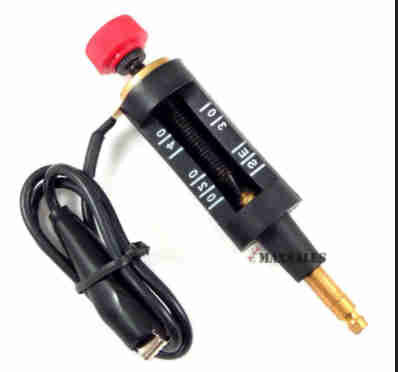
I have a little spark tester I use or you can just hold the plug against the head(I can vouch saying it only hurts a bit if it decides to ground through you).... The little window tester I have is a bit less stress and works great.
My favored tester looks like this...

Yes I have a spark tester, I've 4 different models.

troubleshoot a no spark issue trx350d 1987
in Electronics
Posted
No, I was just curious if he had solved is problem. I like those weird problems.