

dadhustle
-
Content Count
38 -
Joined
-
Last visited
Posts posted by dadhustle
-
-
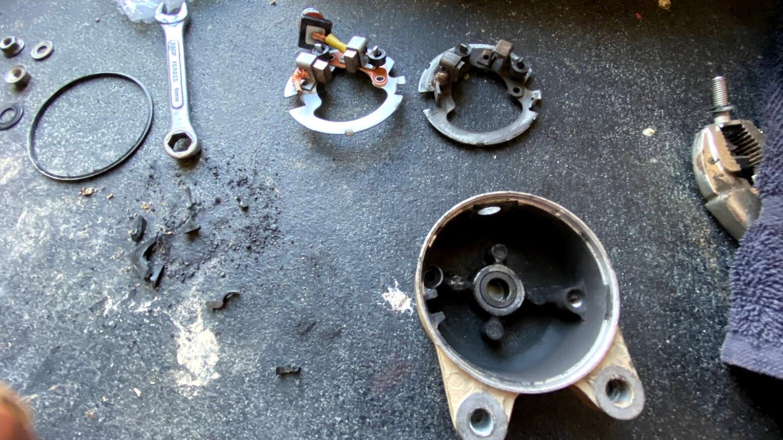
1 minute ago, slowindown said:Definitely agree that it won't work right without a good battery with a good state of charge. A bad battery even on the charger on the jump position often wont work even though it's enough to start the motor. I had to replace the grease in mine last year (02 350). The grease had turned into a gummy tar like substance. I used mobil one synthetic recommended by retro in the link I'll post below. I also cleaned the shift motor. In addition to just adding new grease, you need to pack the little bearings as they'll have crappy grease in them too which needs to be pushed out. You can do that with your fingers. When I finished mine shifted like new. Be careful when taking the cover off, one of my bolts had rusted itself in which caused quite a pain in the butt removing after it broke off - I think that's fairly rare because I couldn't find any posts about it other than mine. I'll add retros link and a couple of pics of what the old grease looked like.
Great advice and detail -will do! thank you @slowindown
-
24 minutes ago, Fishfiles said:Couple of things come to mind , the battery has to be in a fully charged condition for an ES or FE to work properly , so maybe get that new battery before going any farther ----- so did you remove the shift motor , clean it out and re-grease it ? doesn't sound like it from what I read , I think I would go there next
Thanks @Fishfiles I did not last night, but in the course of this long thread.. yep, been off several times and has been greased -upon inspection of all shift sensor area gears and that visible, externally of the shift motor -all look good, not chipped/missing teeth.
-
 1
1
-
-
12 hours ago, freebo86 said:
Have you pulled the shift motor to inspect it? My shift motor crapped out on me a few months back.. couldn’t shift.. locked up in gear. The magnets completely destroyed inside the armatureHi there thank you and update -you may be onto something. -I tinkered w/this so long I drained the battery a bit (note to buy a better battery). After a night of charging, we have tested again this morning; things I notice:
She will shift, but not entirely -will read a - - on the display. You have to rock it a bit and then she'll shift into gear.
After shifting into gear, the switches will not shift again.
To gain another e-shift, we turn the key off and on again -we can get a shift, but only one. -the cycle repeats.
This is true for any matter of shifting R>>N N>>R N>>1 1>>2
I'm stoked though -she shifts!
Given this info, what do you all think? -Position sensor, shift motor? -someone said shift drum, I hope not!
-
2
-
-
5 minutes ago, freebo86 said:
When you were shifting was the bike stationary? If so, just rock the bike back and forth and it will lock into a gear and the indicator will update and hopefully show a grear #.
Id your shifting up and down while bike is stationary it is normal for it to go maybe like 1, 2 and then - - until you rock it where it locks into gear.
For reverse did you push the pin, pull the brake and then try going into reverse? You can’t go in reverse unless you depress the little pin by the left brake lever.
Hi there, I think I did, but truth.. was so pumped, I dunno.. I did get it back in to N but emergency shift, but now I’m back where I started, no action in the shift switches and I can’t get the reset procedure to kick again
-
Okay, spoke too soon. She wasn’t shifting in order, couldn’t get into reverse... odd. Tried procedure again and now she won’t get our of - - instead of neutral.... its a great day though, confirmation all parts work!
any thoughts on this reset procedure?
-
Ooooohyyy Gosh, it worked!
key off>> hold up/down button>> key on, let go soon as it comes on>> heard a shift below >> hold throttle open>> let go off throttle.
display did not go back to N, but pushing switches, she is shifting!!!!!
Thank you Lord and thank you all here!
-
1
-
-
You know, I thought about that tape all day! I just checked though, with manual shift, the light goes out, so I think we’re good there?
The previous motor owner got back to me, say yellow wire was about ignition, but not shifting.
He said, make sure you preload the shift sensor. Not knowing what all that was, I started googling.. not finding my year, but am seeing something about hold both shift switches as you turn on..... to reset the ecu... make any sense?
-
1
-
-
10 minutes ago, retro said:The green Neutral light indicator is centered at the top of the display under the tape. Like this one:

Take that tape off and see if the neutral light works while the trans is in neutral.
Oh good Lord.. so it is.. well this will give everyone a laugh... having a drink and calling it a night.
Oh and light is all lit up! I’ll get on the switches AND shift sensor?
-
1
-
 4
4
-
-
Thanks, I will definitely look into oem switches and shift sensor before the ecu.
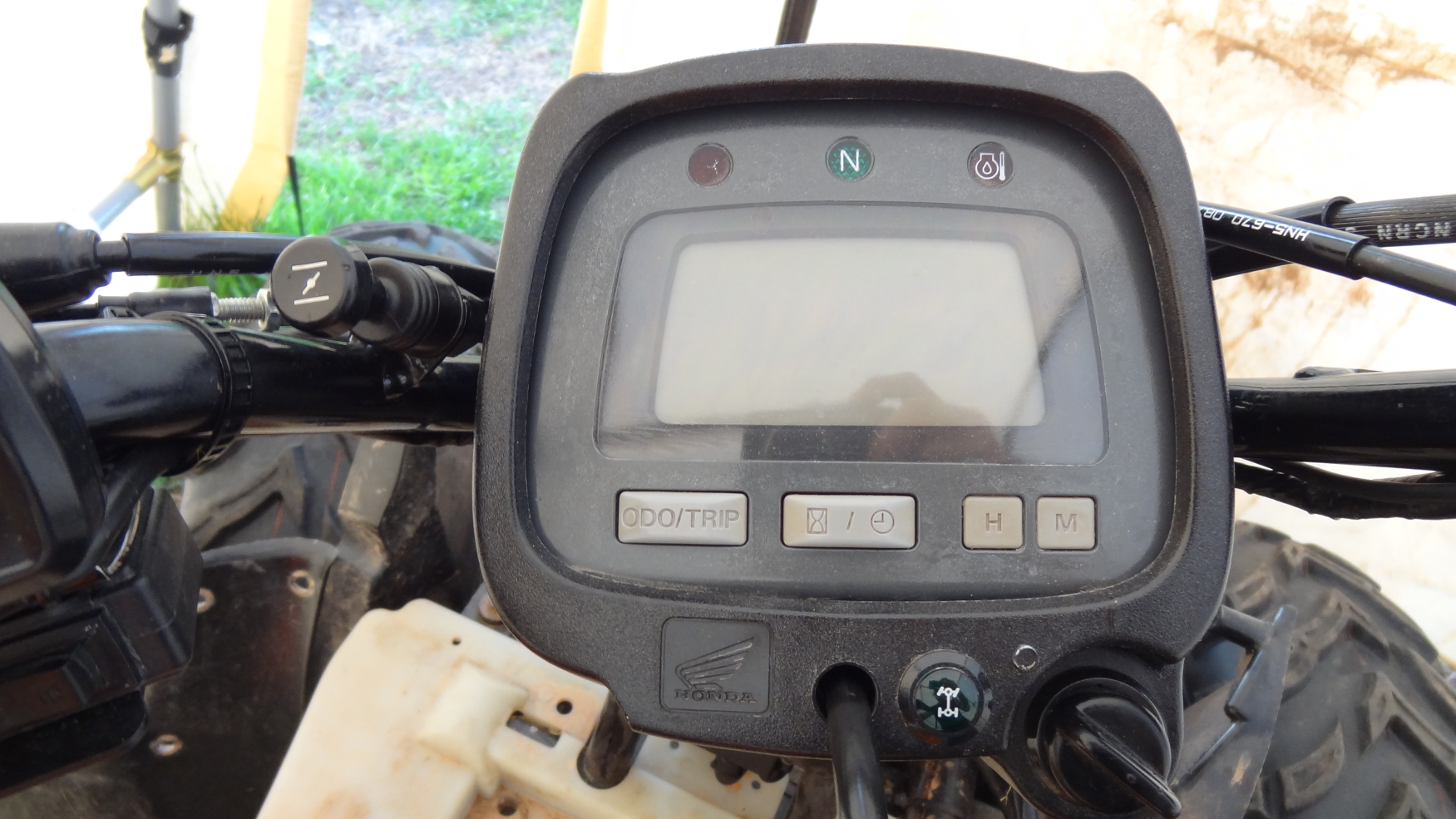
I want to show you our dash, not to belabor the point, I just want to know if I should have something else. As you can see, we don’t have a green light.. could something else be happening here?
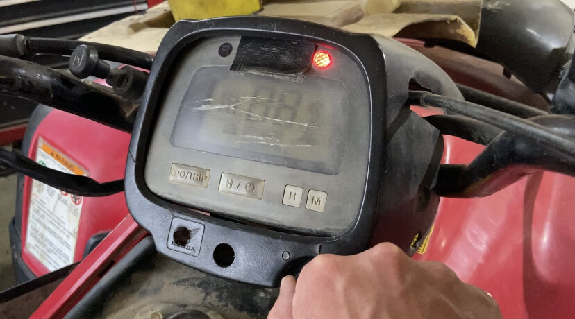
pic immediately after turning on the key
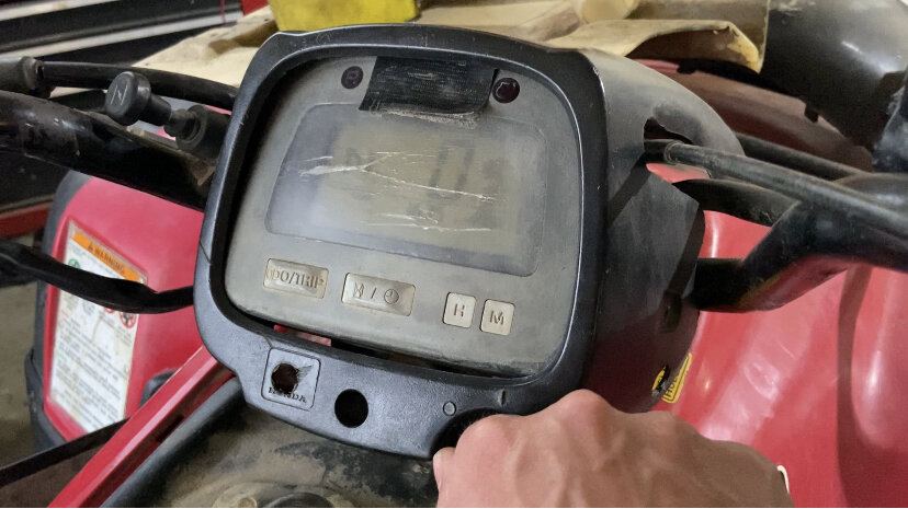
pic after temp light goes out? Hard to see, but we have a neutral reading on the display
-
1
-
-
7 hours ago, retro said:Yes, by now you should already have had that ECU out in your hands many times and have been testing wires between that connector & the angle sensor & shift switches!
Let's recap what is required of the ES system though, because a shift ECU is a very expensive part! And I am very uncomfortable when advising members to buy expensive parts! So let's double check everything, it only takes a few extra minutes. Please read this thread again from the beginning up to this point?
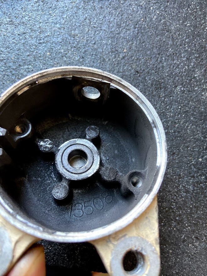
Looking back you'll see we began diagnosis by verifying power supply and grounds before we did anything else. Check all three of your grounds again, the black negative battery cable bolts down to the rear motor cover above the recoil starter, then that same black cable continues to where it bolts down to the right-rear of the frame near the shift ECU. The wiring harness ground is bolted down to the frame near the ignition CDI, on the right-front side of the frame. Make sure that all three of those grounds are clean and tight.
DH: Grounds look good; one by the ECU was a bit dirty, but cleaned up -no change
7 hours ago, retro said:ES Requirements:
- Battery must be fully charged and in good condition
- The 30 amp "Main" fuse, the 30 amp "Motor" fuse and the "Ignition" fuses must be functional
- The Neutral light must be on while the transmission is in neutral while the ignition switch is turned on
- The reverse gear lockout cable & lever must be attached and be functional (located lower-center area of the rear motor cover)
- The reverse switch wire (located on the left-rear of the rear motor cover) must be plugged in
- The vehicle speed sensor must be plugged in
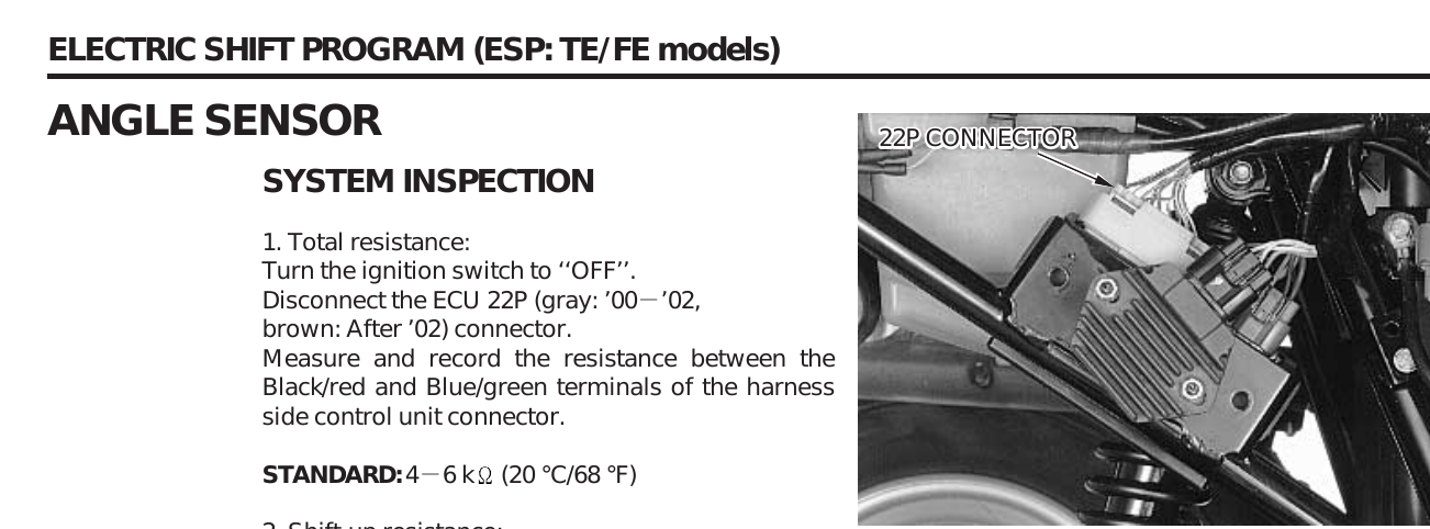
- While at rest in neutral, the Angle sensor resistance must measure between 4k ohms and 6k ohms for shifts to initiate
- The shift motor must be functional and you must be able to shift the gears manually.
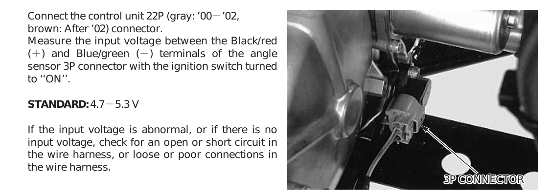
- Supply voltage for the Angle sensor & the handlebar Shift switches must measure between 4.7-5.3 volts
- The handlebar shift switches must be functional
DH:
Battery -check
Fuses -check
Neutral light -we don't have one -we have a R light and N on the digital panel -stays in N on the digital panel -is that the same?
Reverse gear lockout cable and level -I searched the manual over for this. I'm not sure I've found it, but its the cable that sit on bottom center of rear cover, sits in a guided harness, a collar of sorts on the cable -I'm near positive its for the reverse (attaches to circled in picture below?)
Vehicle speed sensor -check
Angle Sensor resistance -check, holding at 5+/-
Shift motor functional -check, verified several times w/12v direct to motor
Supply voltage -fail, holding steady at 4+/- here
Handlebar switches -TBD, but not looking good
7 hours ago, retro said:We learned that the supply voltage (Black/Red wire from shift ECU) for the angle sensor and shift switches measures low, at only 4 volts DC. You measured again while the battery was connected to a battery charger to insure that low battery voltage was not the reason why the ECU supplies only 4 volts.
We learned that the handlebar shift switches are not functional because resistance through each UP/Down switch measures high at 8 ohms. So.... you bypassed those shift switches by jumpering between the Black/Red wire to the Blue/White wire and then between the Black/Red to the Yellow/White inside the wiring harness shift switches connector, attempting to initiate a shift. That test failed, presumably because the supply voltage measures below specification, at only 4 volts DC.
So, since the ECU will supply no more than 4 volts to the angle sensor and the shift switches, we must conclude that the ECU have failed.
Double check everything though! Because it will be your wallet, not mine, that will pay for the repair part that we have determined that your Rancher needs. If you have any questions or concerns, please continue to ask them? 🙂
What do you think? ECU? -honestly, my son is growing discouraged, so its push over the hump here or sell it off 😞*Something occurred to me; I bought this lower motor half used --too long a story to go into for now. The guy that sold it to me (whom I'm trying to reach for deeper understanding) said something about jumping a yellow wire "you'll never read it in the manual" he said ...this was regarding ES. I dunno if this helps, but it struck me today.
Thanks @retro,
RD
-
11 hours ago, retro said:Ok, according to your measurements the angle sensor resistance is within range of the spec and so the angle sensor should allow the ECU to initiate shifts.
However, the voltage supplying the shift switches and the angle sensor (Black/Red wire) is low. You measured 4 volts DC while the minimum spec is 4.7 VDC. You also tried to jumper between the shift control wires (bypassing the shift switches) and that test failed to initiate a shift. This indicates that the Shift ECU is probably bad.
The shift switches are probably bad too, since you were measuring 8 ohms resistance through each of them while depressing the Up & Down buttons.
Thank you @retro!! -appreciate your help through all this! -by shift ECU, you mean the 22pin/gray connection ECU under the right rear fender? -you advised the Amazon shift switches were probably bad in a previous post; we'll get them replaced.
-
Thank you, I’ll try to explain what I did:
testing the shift switches:
multimeter set to ohms with audible continuity (20k), tested by touching probes
Removed gray ecu harness, connected multimeter probes as such:
Black probe to red/black wire
Red probe to blue/white and then yellow/white.
Depending upon red probe, toggle shift switch, gathered the reading.
For the shift sensor voltage, unplugged from shift sensor, with ecu harness connected and key on, multimeter set to dcv 1000, returned a reading of 4.
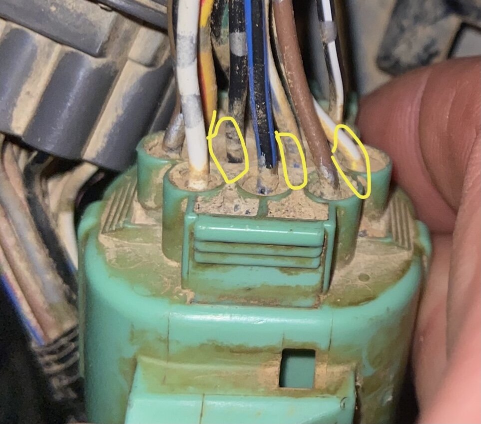
For the resistance of the shift sensor, ecu harness disconnected, shift sensor plug connected to the shift sensor and multimeter set to ohm 20k, I checked the green/blue and red/black... green/blue is 4th down from opposite row of red/black? I would call it left looking down on the wires.. reading is 5.09.
I hope this helps, welcome any guidance.
-
Hi there, providing a more clear explanation:
Hope the following proves helpful and thanks for your persistence.
When re-testing continuity in the e-shift buttons (at the ECU end), we received:
White/Blue >> Black/Red (UP)= 2.98-4.14
White/Yellow>>Black/Red (Down)= 3.14-4.25
*tested several times and received in this range
Was this volts DC measured with the key on? Or was it Ohms resistance (Continuity) measured with the key off? Please explain....
DH: I've performed both ways; key on and off. Measurements as follows:
- White/Blue>> BlackRed
VDC = 0
Key Off Continuity = >4 <6
Key On Continuity = >3 <4
- White/Yellow>>Black/Red
VDC = 0
Key Off Continuity = >3 <4
Key On Continuity = >3 <4
*Each continuity test performed several times, readings ranged in above
When re-testing continuity at the shift assembly end, both tests returned in range of 8.00
8 Ohms resistance while depressing the shift switches, measured while the switches assembly were unplugged from the main harness?
DH: =No, this was done at end of shift harness, unplugged from main -point I guess 🙂
When testing the shift angle sensor (at the connector end), voltage ranged from 4-5 *several tests)
When testing the shift angle sensor (at the ECU end), voltage was also in range of 5
I am confused here as well. Where/how are you measuring voltage when you say "at the ECU end"? This test (unplug the angle sensor and measure voltage inside the angle sensor main harness connector with the key on) is all that is required:
DH: tested again, 4VDC
When you provide measurements please include whether those numbers are volts DC, or Ohms resistance?
DH: Roger
Did you forget to include this test....? With the ignition key off, the angle sensor plugged in, unplug the ECU and measure resistance through the angle sensor like this and report back:
DH: Key off continuity = 5.09
-
Good Day All,
Okay, we have tested as guided above; here's what we know:
*All tests were performed w/the battery connected to a charger
When re-testing continuity in the e-shift buttons (at the ECU end), we received:
White/Blue >> Black/Red (UP)= 2.98-4.14
White/Yellow>>Black/Red (Down)= 3.14-4.25
*tested several times and received in this range
When re-testing continuity at the shift assembly end, both tests returned in range of 8.00
When testing the shift angle sensor (at the connector end), voltage ranged from 4-5 *several tests)
When testing the shift angle sensor (at the ECU end), voltage was also in range of 5
I believe I followed instructions, but I'm so lost now.
*I did remove the ECU and noticed some rust on one of the pins on the 5 connector harness. I tried to clean that w/some blaster and wire brush, but it didn't net anything.
Please share your thoughts and thanks again.
-
Thanks @retro we have just tested, we don’t see any shifting, up or down. We held our hand on the shift motor and feel nothing, nor see any change in the lcd panel
Below is a pic of the wires jumped, red-black>>white-blue and red-black>>yellow-white. Correct?

-
Okay, finally!
Valves are adjusted
Solenoid in
She starts and runs.. pretty well
No e-shift. I've gotten to a point of testing as directed by @retro. -I have 0 continuity from the ECU connector to the shifter. I understood the instructions to then have me test continuity of the same cables in the shifter plug...0 continuity.
I also tested the voltage of the shift motor connector = 4v -should be min 4.7 per KB..
What do you think? -all this, to learn the Amazon shift paddles/harness is bad?
-
2
-
-
Hi guys, solenoid is here and I’m trying to surprise my son.... back to working on the valve adjustment while waiting for him.
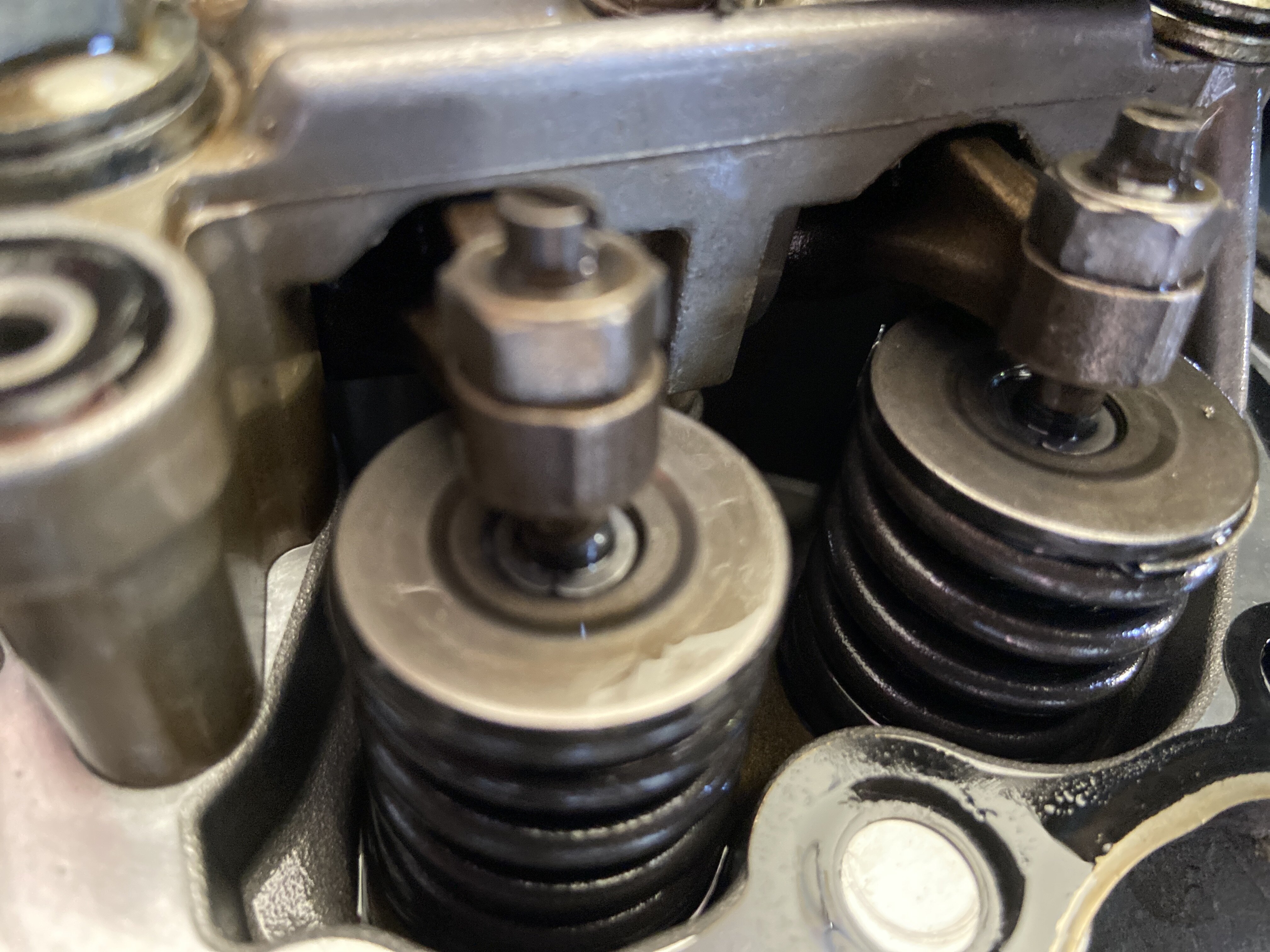
Previously, you guys mentioned, tdc on the down stroke and that the guides would be moveable..
I’ve cycled around to tdc and the piston is top (smallest clearance) in cylinder. Is this correct? Only one of the guides will move (one on right), in picture.
if I cycle to tdc with piston at bottom of cylinder... neither are lose.
what am I doing wrong?
update: thing I’m good.. took it apart, saw visible differences in screw setting.
just wanted to spare folks from responding.
Thanks All
-
29 minutes ago, Fishfiles said:dad' , if PowerSportNation doesn't have anything for you at the moment , I have learned a trick to save a lot of money on solenoids and still go OEM , the correct number for your 2001 350 is 35850-HF1-670 and it sells for $86.78 at Partzilla , the solenoid for a 2007 420 is part # 35850-HP5-600 an sells for $25.92 , they are the exact same ,except for the colors of the two small trigger wires , on my 300s and 450s they plug right in an work --- and I have put one on my buddies 2006 350 and it worked on his
Thank you, I'll tuck that away.. PowerSportsNation had one -7.26 + free shipping!!
-
29 minutes ago, retro said:You can get a good used solenoid from Powersportsnation pretty cheap, shipping is included in the price:
https://www.powersportsnation.com/saas/pliable/searchresult/?search=Rancher%20350%20solenoid
Thank you, for the prompt reply and guidance! Ordering today!
-
Hi Gang, I'm back -battery charged and ready to resume @retro testing.
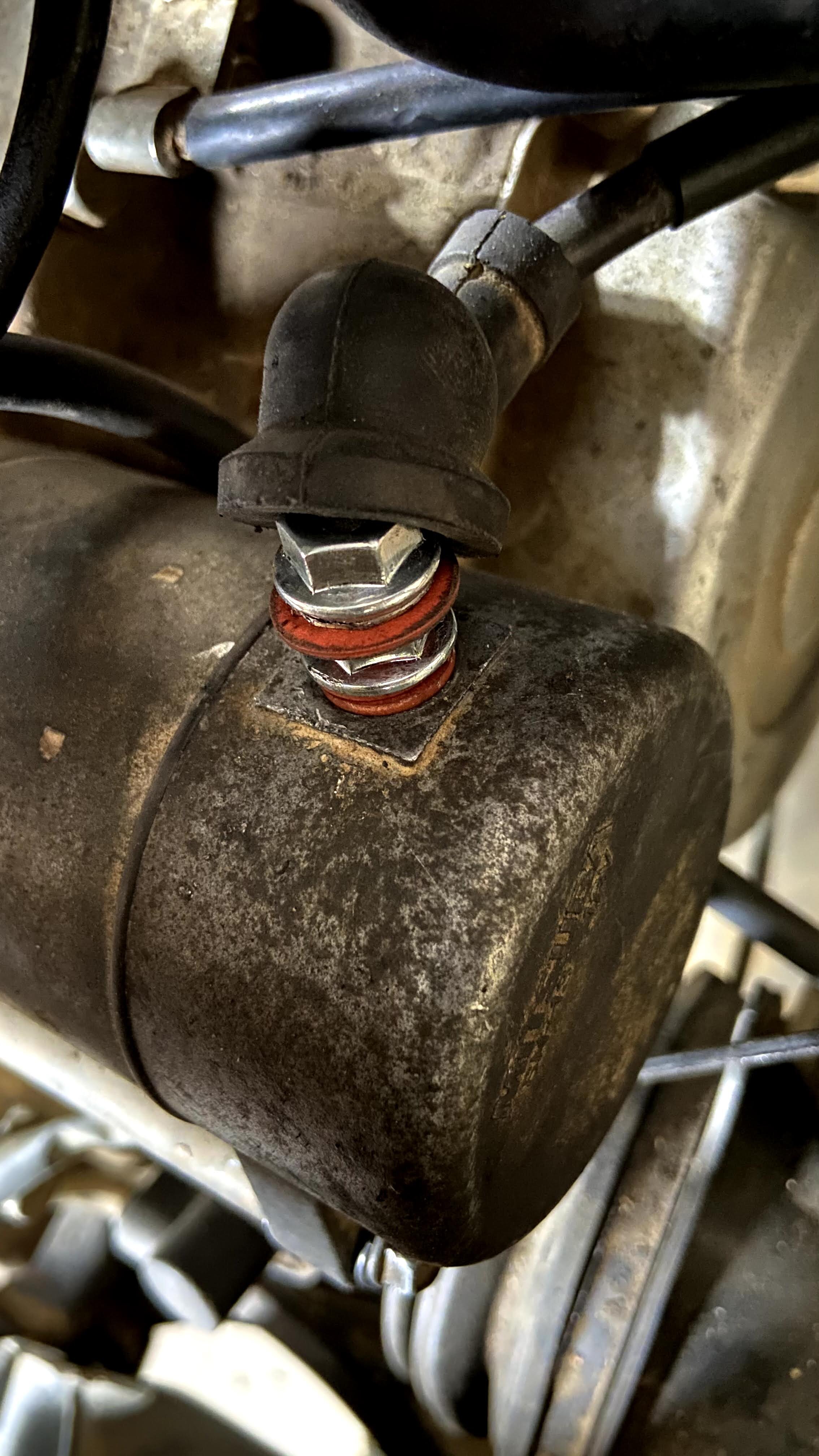
-I'm stumped and need to divert just a moment. in attempting to connect the battery, soon as I touch the positive terminal, she tries to crank as though I'm pressing the electric start button. -would seem to be I've closed a loop some place, but I don't know where. Below are photos of the connection to the new starter kit and a markup around the black plastic bezel that sticks through through the starter post opening. I point this out as I don't think I'm contacted there.
Any ideas??
-
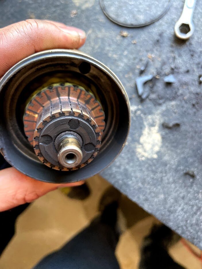
Okay gang, so an update -thank you to @jeepwm69 -rebuild kit arrived quickly and we installed today. -installed in no time -I think its safe to say it was needed (below) -I just hoping the starter isn't now shot.
Now we wait on a battery charger (should be today) and then I hope to get back to testing as guided by @retro
Hope to report advancing news soon!
Any thoughts here are appreciated!
-
1
-
-
On 4/9/2021 at 7:20 PM, Fishfiles said:Sometimes jumping around can be bad , one of the easy thing you pasted by , could be the ring at the end of the ride , a ES is very dependent of a full strength battery
Hi @Fishfiles I don't follow do you mean, that I need be certain the battery is fully charged?
-
On 4/8/2021 at 11:25 AM, jeepwm69 said:How tight did you tighten that starter cable down? If you got crazy with it, you might have broken the insulator on that starter cable stud where it's grounding out on the starter case.
If you look at this brush/ rebuild kit for a starter, you'll see there are plastic insulators which keep the stud from touching the metal case on the starter and grounding out. If you overtighten that it can cause the stud to ground out on the case, which would do what you're saying yours is doing.
Rebuilding one of these starters is super simple. I'd take it off and look it over before you go tearing into a bunch of stuff.
Thank you for this! I realize I’m all over the place, but I previously mentioned the post being “loose”, wobbly on the starter. I didn’t tighten ALL the way down!
I hope this just drained my battery, not cooked it.
For 13.00, I’ll give this a shot!
Hoping to get back to es testing soon!
-
10 minutes ago, freebo86 said:
At TDC compression couple of things you will note,- You can wiggle the valves a bit back and forth by hand. On exhaust stroke TDC they will be very tight.
- your cam lobes will pointing down.
Sequence of events as you turn the flywheel or pull the starter rope:
exhaust valve opens, exhaust valve closes - T shows up but this is exhaust stroke.
intake valve opens, intake valve closes, T shows up again. This is compression.
Ahhh, good to know! Will be a couple days before I can get back into, but will share back.
Thanks for this and the battery suggestion!
-
1
-


'01 350 ES, so many new parts, won't start
in Electronics
Posted · Edited by dadhustle
Just wanna say thanks again to all. Final update, I removed the amazon shift sensor and replaced with original.. she shifts, all 5 gears and reverse! Now and again she won’t, putting back on, the old switches didn’t help.. so that and a battery has been ordered!
I have witnessed my son riding around 1st to 3rd! So it does seem, we are on the right side of things.
She’s now backfiring, but atm I’m chalking that to our poor riding. I’ll start a new thread if this become an issue 🙂
Oh and I will definitely follow the provided guide!
Great community here, very grateful to have so much help.
God Bless All,
RD