

Goober
-
Content Count
1,301 -
Joined
-
Last visited
-
Days Won
4
Posts posted by Goober
-
-
I like the idea—want one for our outdoors. If you’re on clay and get soil expansion, the point where the new deck attaches might work like a hinge. Then, the most likely break would occur at the hinge point. Leave yourself enough room to work if you get a break under there.
we would place concrete at least four feet deep to provide solid footers
-
 2
2
-
-
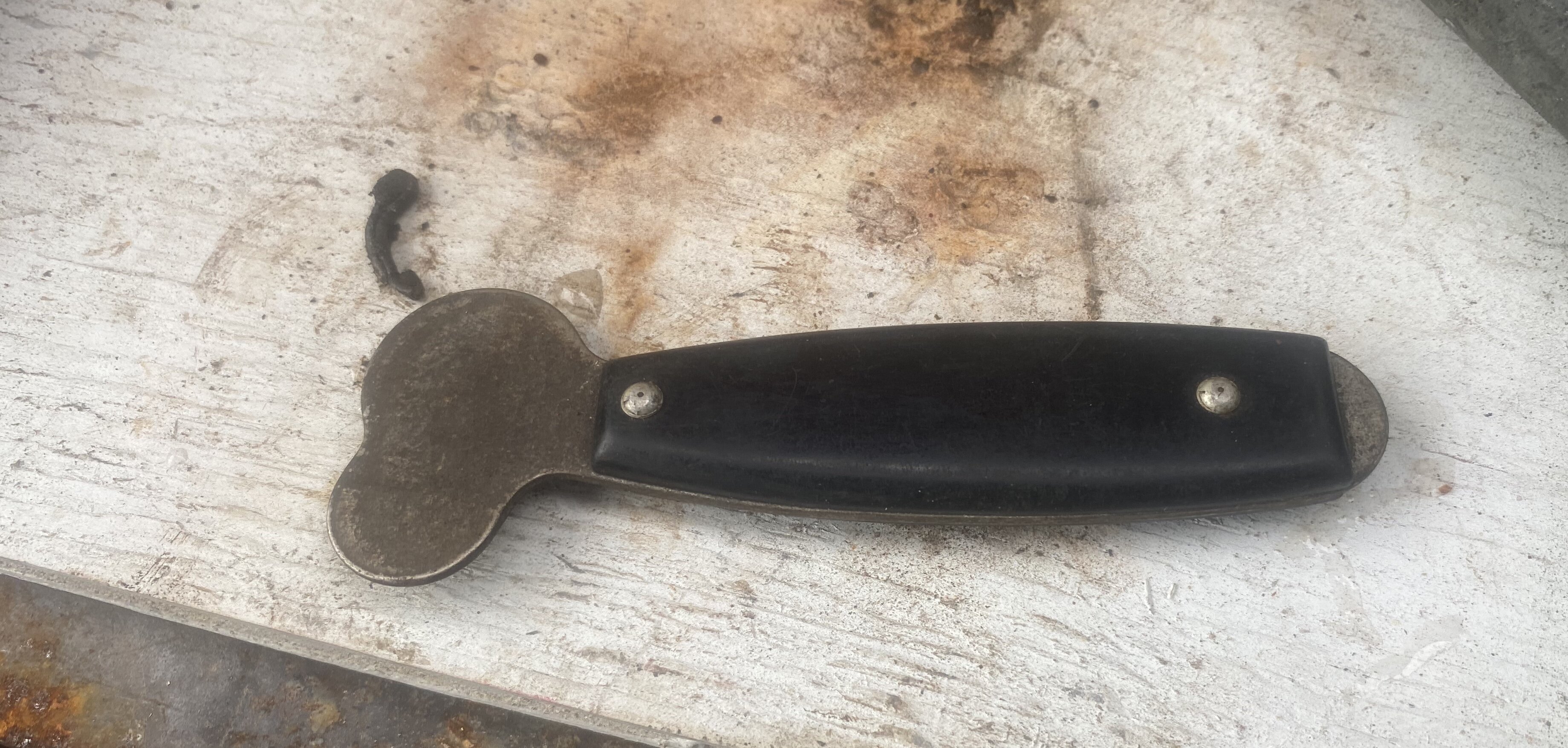
5 hours ago, Fishfiles said:Here is a tool I dug up yesterday , I think it was my Grandfather's , it is old looking and well made , kind of looks like a knife handle , I don't want to poison your mind with what I think it might be , so I will se quiet for now , any ideas ?

It is called a Snoopy. Used to open the doors on aircraft Dzus fasteners. I used them for years
-
3
-
-
What the F, over? I just tried to ask someone on the old board to also post their question here. So i type out atvhonda.com, and the website turns atvhonda.com text to all asterisks! Petty BS
-
 1
1
-
 1
1
-
-
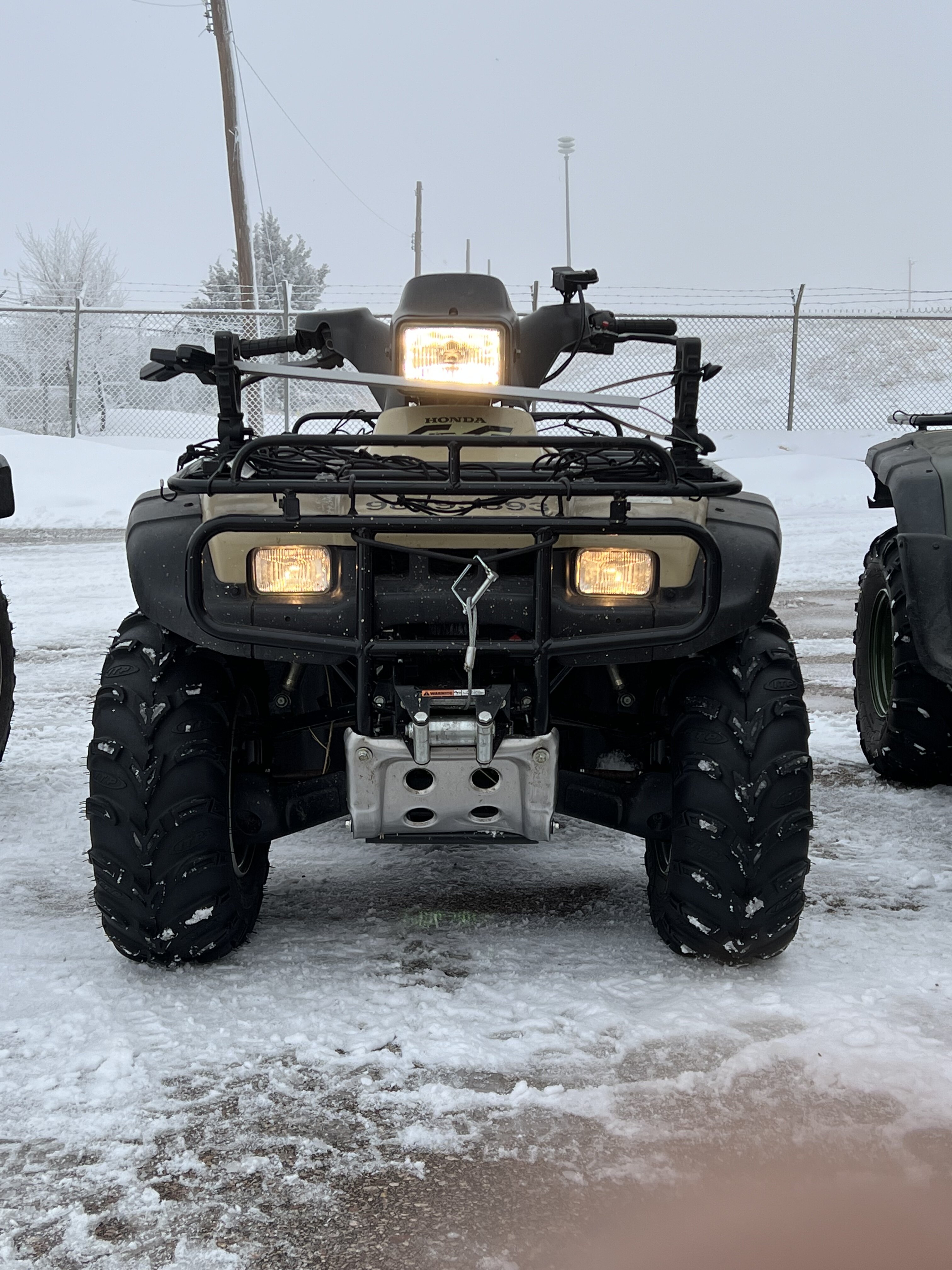
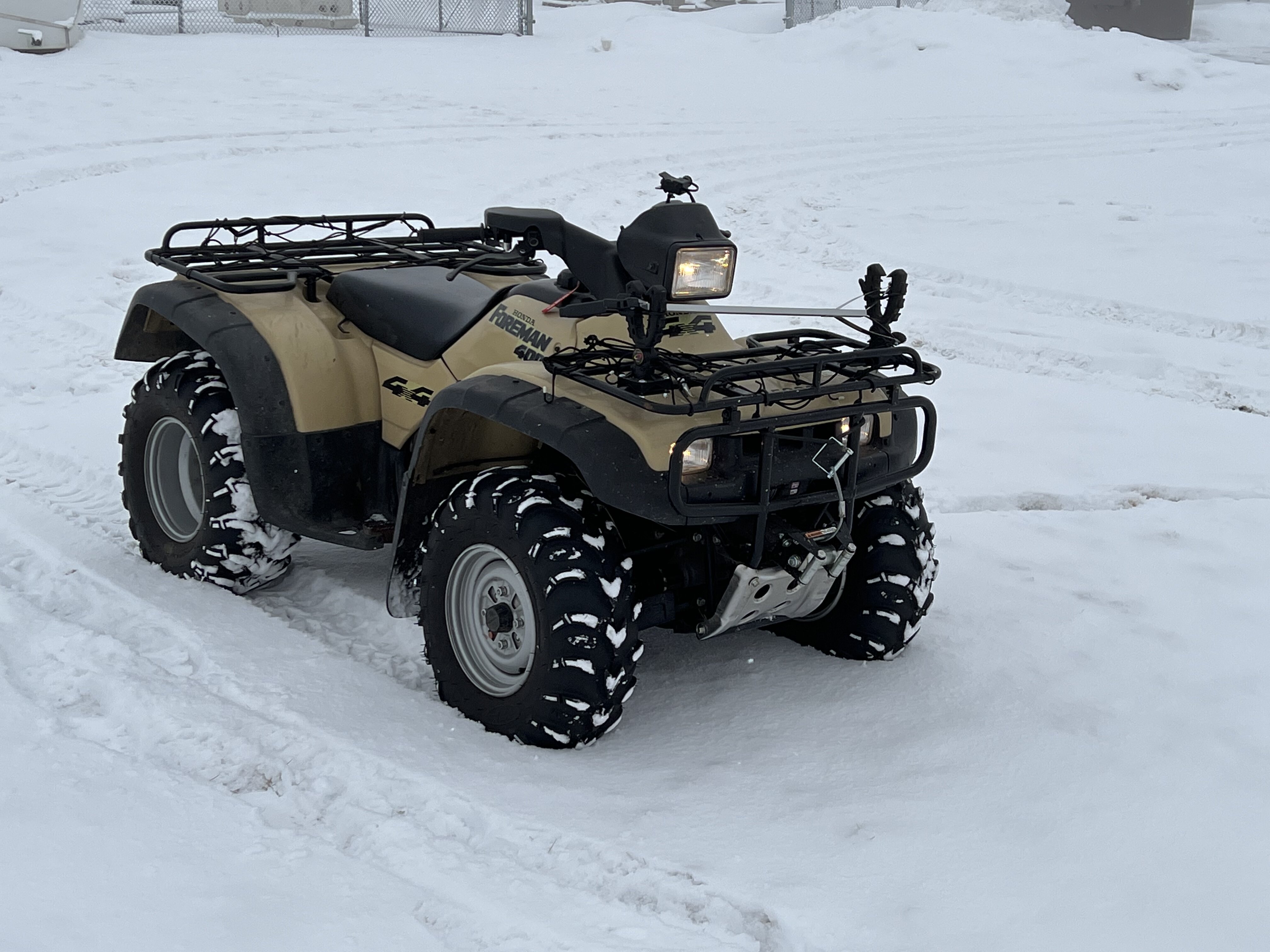
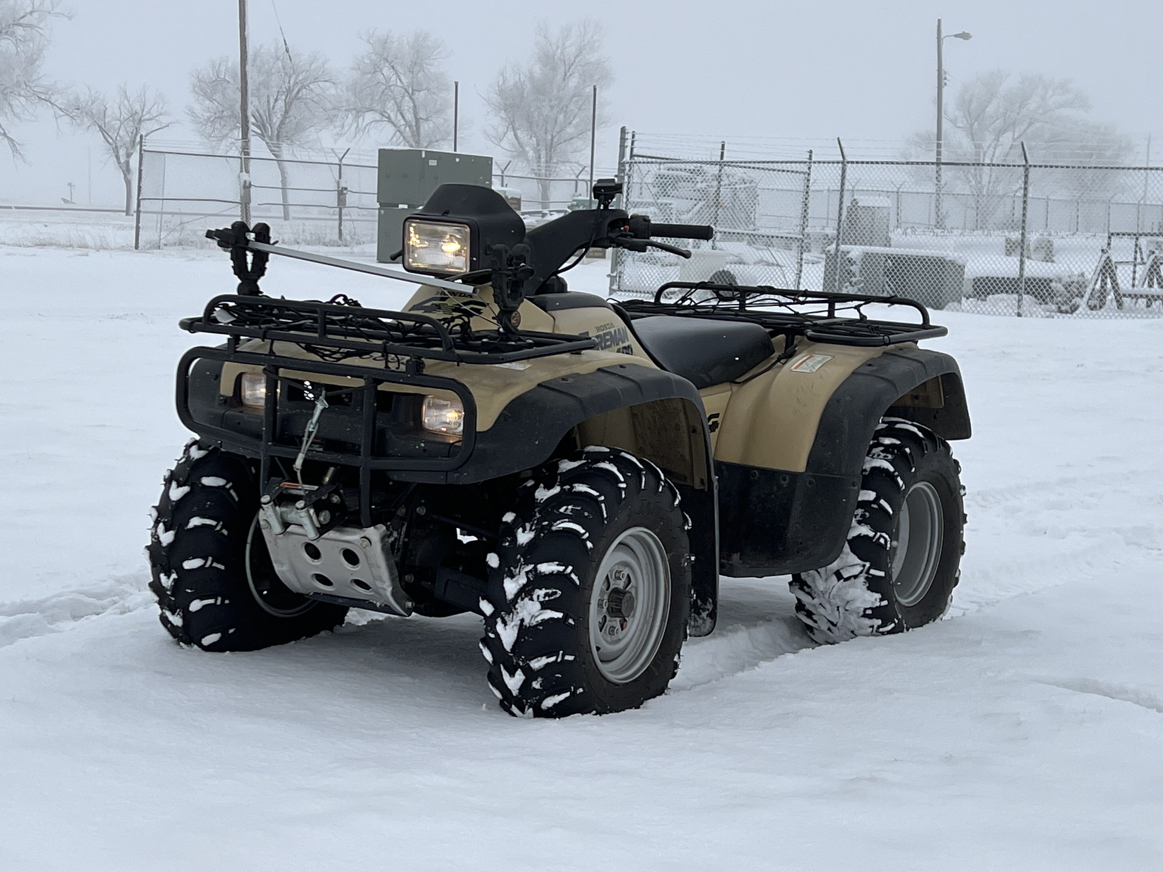
96 TRX400 Foreman. In love with this one.

-
3
-
-
Yup i were joshing ya. I don’t trust aftermarket cuz always something wrong, like the wire colors gonna be different. Or connectors. Then It would gnaw on me like an aftermarket carb with the fuel inlet on the wrong side!
i love my ‘93 i will have to take a pic for ya.
-
1
-
-
Is that what love is? An aftermarket solenoid?😆
Happy Valentines Day honey i stopped by the gas station and got you flowers and sushi because you’re so special! JK
-
ECM
in Electronics
I don’t recall you saying anything about battery condition. These ES models need a very good battery; have you done a load test on it?
-
Yup that’s what I would do—a restoration. Harnesses might be easier to find than heads. A compression check would tell a lot. but you’d have to use a good battery to get er rotating.
-
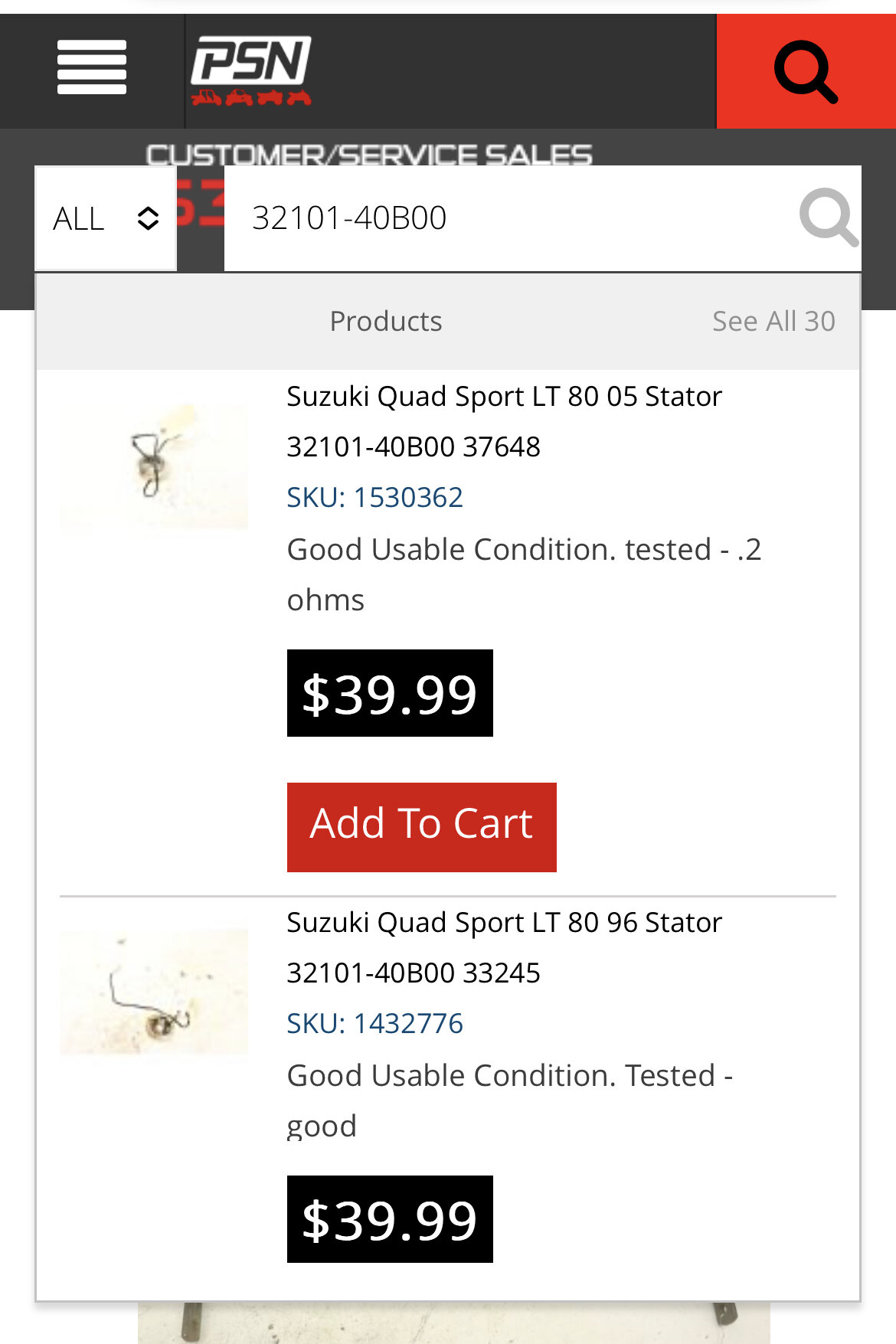
Power Sports Nation has a good looking 97 wire harness for $300
https://www.powersportsnation.com/honda-foreman-400-fw-97-wiring-harness-32100-hm7-611-41018.html
-
1
-
-
nothing much here. Sounds like you’re stuck between wanting the motor for parts or restoring this quad?
-
You’ll find it no doubt. Then you’ll have some hard-to-find spare modules
You have aftermarket fuel pump on it?
the coil may have color codes on the housing. The important thing about a coil is you have primary and secondary windings. The secondary has more windings (usually) and so the resistance values are different.
So if you can’t tell the poles apart. Consult the service manual on coil measurements and put the meter to it.
This is why Fish said to remove the coil spark plug cap. Then you inspect the spark plug wire for corrosion and nip off a bit. Then clean the spike end of the cap with a .22 cal bore brush-
2
-
-
I don’t think you answered my question about the pulse generator. When you measured resistance at the pulse generator did you measure it at the leads under the right side cover? That’s the shortest length of wire through the unit.
if that’s when you got 400 ohms that’s out of spec. -
Thanks for clearing up that he has correct CDI; the other thing i want to clear up is that the 87 TRX350D is the one-year only CDI.
also @Raystrx350d when you “probe the fan lead with 12vdc,” that’s not the same as what i recommended. In the manual “oil cooling system diagnostics” the exact method is to remove the lead as @shadetree said and touch it to the footpeg. This closes the oil temp sensor circuit thru the fan control unit, which energizes the fan circuit.
Being inexperienced at troubleshooting, you’re still trying to understand component nomenclature, principles of operation, troubleshooting techniques and the problems with aftermarket parts. Don’t give up just yet. Rely on the manual—read the troubleshooting guides.
Also i would not use probes that pierce the wire sheath; is that what you’re using?
-
1
-
-
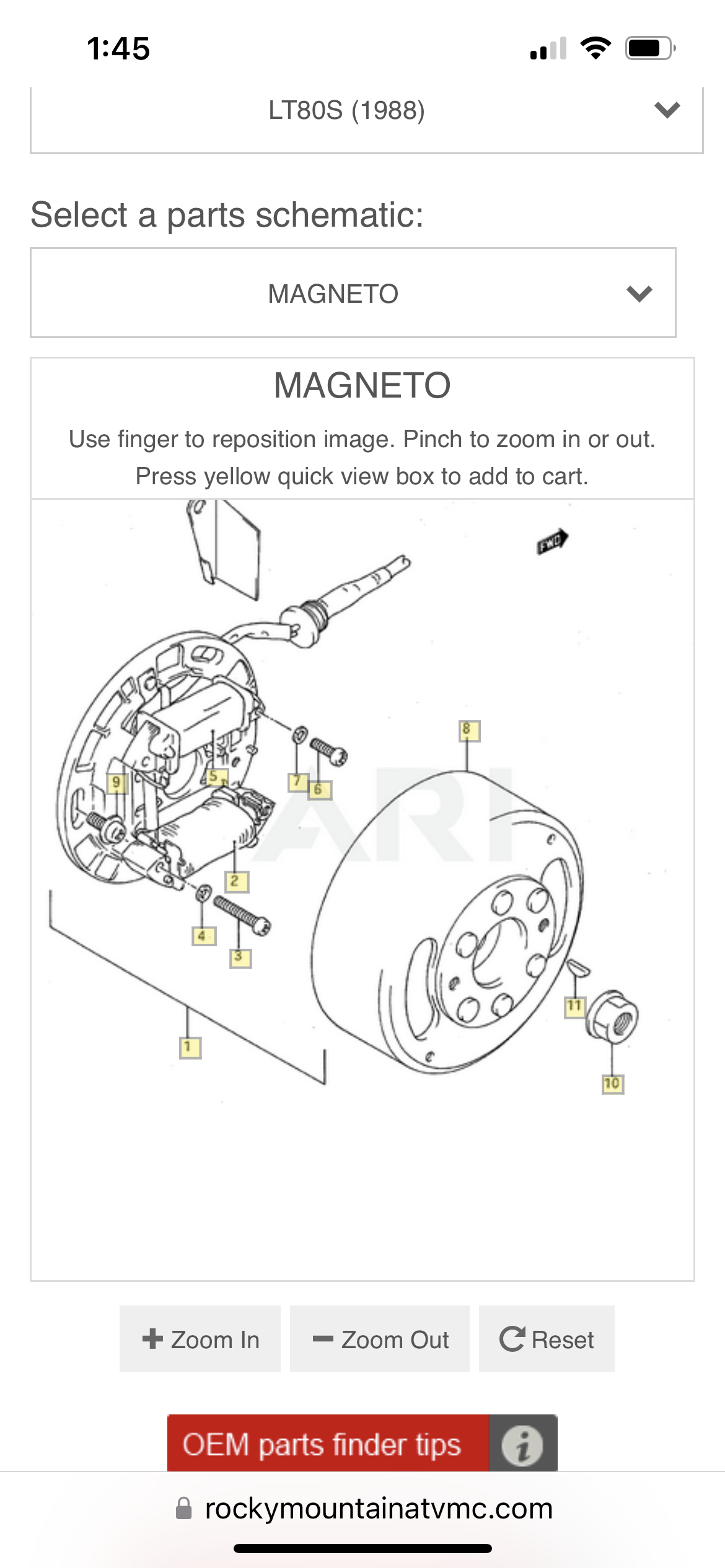
Power Sports Nation has two; you need the cover, bolt, woodruff key etc. as well?
https://www.powersportsnation.com/used-parts.html?utm_source=google_cpc&utm_medium=g&utm_campaign=10603085898&gclid=EAIaIQobChMIz5v51oKv_QIViimzAB0JMAWUEAAYASACEgIS4fD_BwE
use the oem parts finder at Rocky Mountain atv and Partzilla
-
1
-
-
Bummer. The stator isn’t scraping on the flywheel?
-
A little mistake like having the coil leads switched is easy to check. The color codes on the coil are hard to see
-
1
-
-
At least you’re learning the ignition system!! Are you gettin a new pulse generator?
While waiting for parts, continue to inspect and perform electrical checks on wires you may have jostled while doing your other repair work. Use the schematic to double check the kill switch at all those connections on the right front of the quad.
get some contact cleaner, permatex dielectric grease and a few plumbers flux brushes. Maybe a brass and nylon gun cleaning brushes. not steel brush. Disconnect and clean all those connections while you’re doing continuity checks—apply a thin film of the grease on the electrical contacts and the backshell of the connectors—you’ll find they snap together and disconnect more easily.
Look for weak wires on the harness and subharness. every time i went to start mine i had a steady neutral light. When i cranked it the light would go out. So I swapped the neutral and reverse leads and tried again. Of course the reverse light came on steady and i got it to start—that was a hallelujah moment, because i knew the malfunction was isolated to the neutral wire portion of the circuit. i found the neutral switch connector wire hanging by 2-3 strands.
Does your fan come on? Disconnect the oil temp sensor lead and touch it to the footpeg. The oil light should come on steady and fan should come on
-
2
-
-
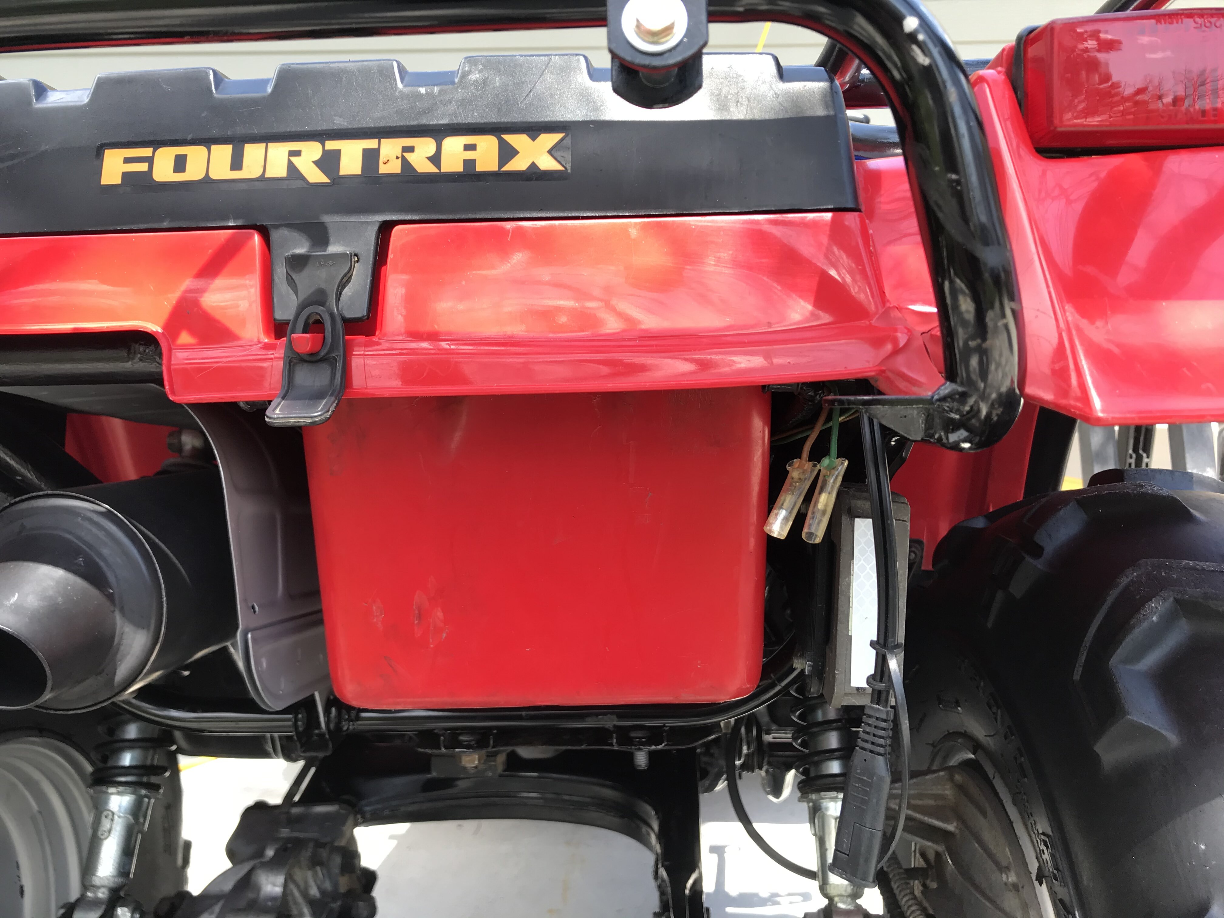
For 86-89 TRX350. Did you know there’s an accessory lighting connection on the rear of the quad? You can find it on the main harness near the right rear taillight—wrapped in blue tape.
it will energize with the lighting circuit switch.
-
4
-
-
15 hours ago, Raystrx350d said:It also said to text fuel pump wires for voltage.. I have none!! Tested the fuel pump straight 12 volts it works . What will kill the voltage ?
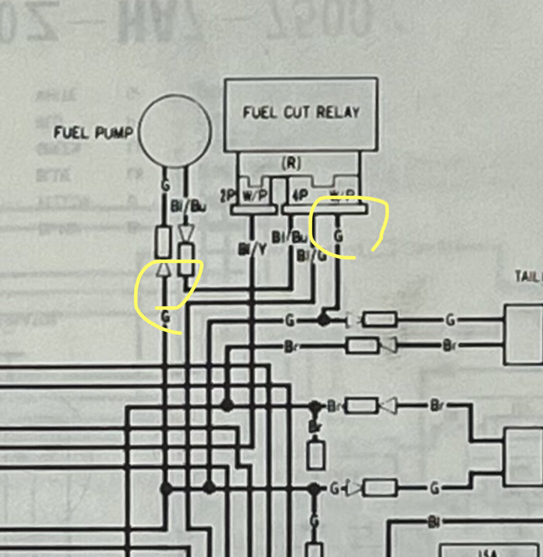
Well two things I know of. The fuel cut relay could be malfunctioning or the ground is bad (circuit not complete). Keep reading. if you already changed the fuel cut relay (oem). Then inspect the green wires for damage and try wiggling them while you have the jumper wires on.
test fuel pump circuit grounds for continuity : red lead of meter to green wire connection leading to fuel pump (not pump wire). Same on cut relay connector terminal (not relay). Black meter lead to a bolt on the frame. Should get continuity.
-
1
-
1
-
-
You said you got a new fuel relay already?
the resistance is a leetle high on the pulse generator. Did you check it at the leads under the right side cover or CDI?
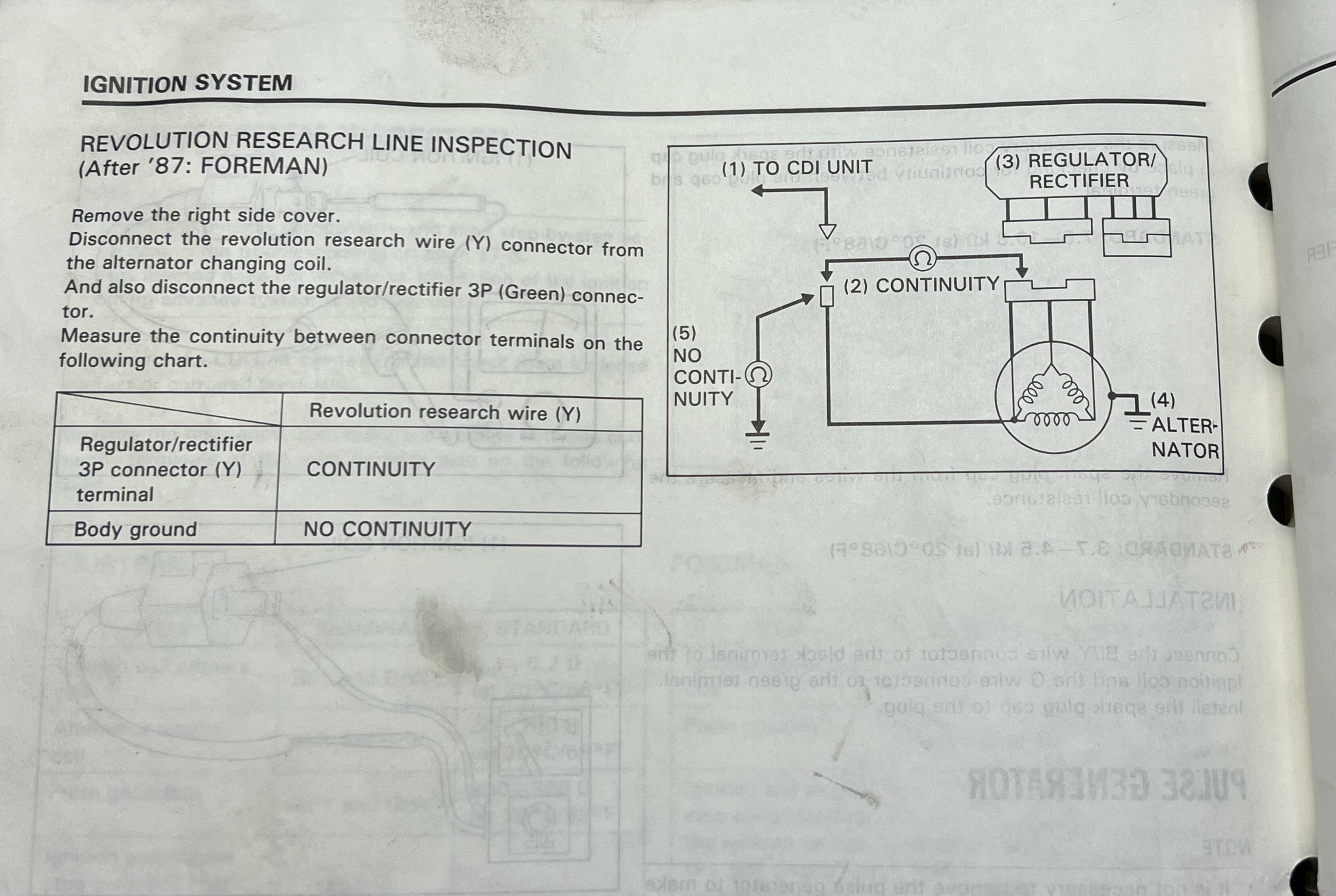
for the RRL Y wire you’re only checking for continuity from the Y wire thru the 3 other yellow wires at the stator 3-p connector (3P). You can measure resistance but it will vary with temperature.
then test for continuity from the Y wire to body ground—you should get zero continuity. OL on your meter.
edit i put a confused emoji on your comment i didn’t know what you meant by engine side.
-
1
-
1
-
-
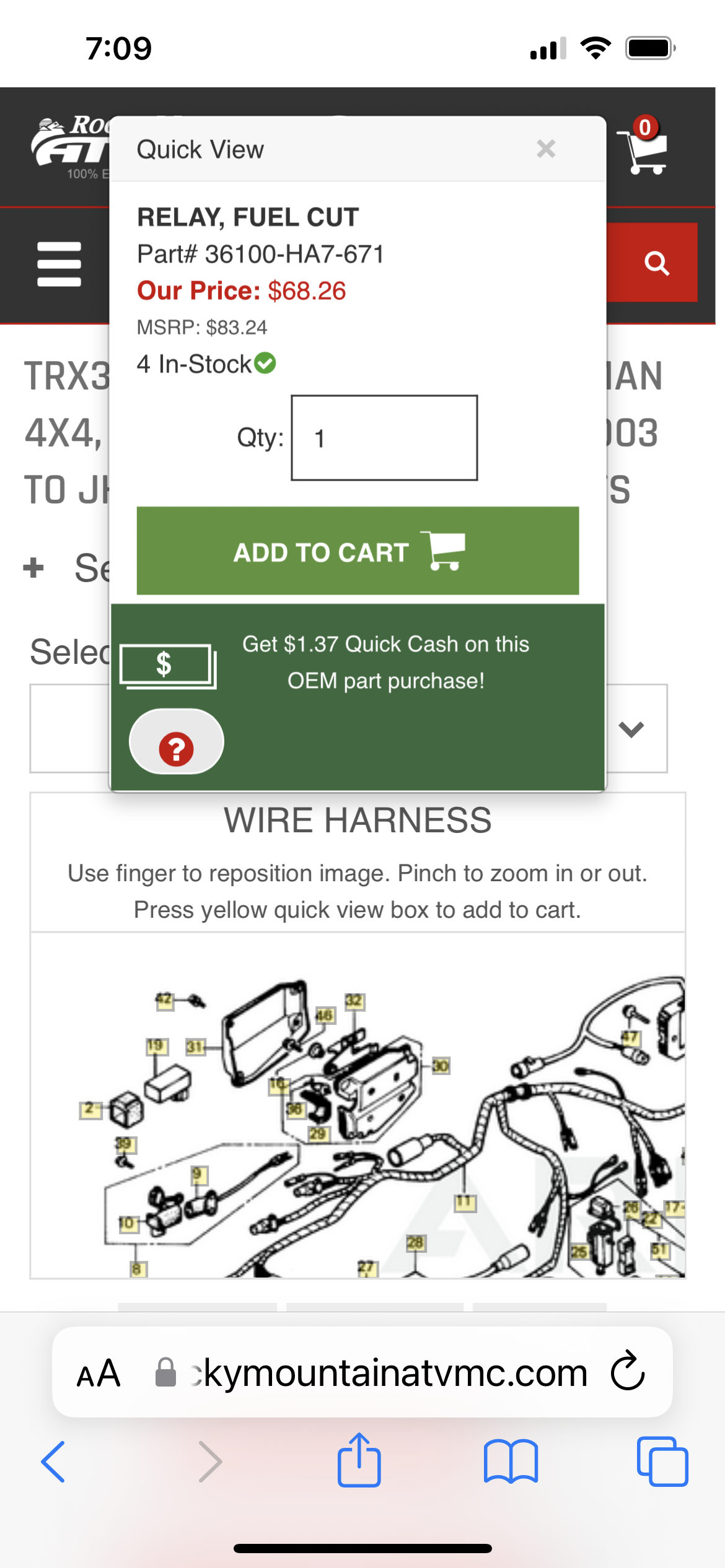
If you need a fuel cut relay, Rocky Mountain has the $70
use the oem parts finder at Rocky Mountain atv and partzilla
i tried to paste the link but website not having it.
-
1
-
-
Check RRL Y connection. It should be a single Y wire coming off stator—separate from the 3 yellow wires coming off stator
-
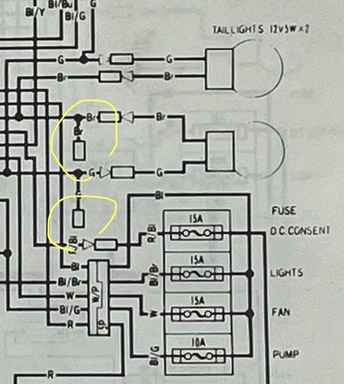
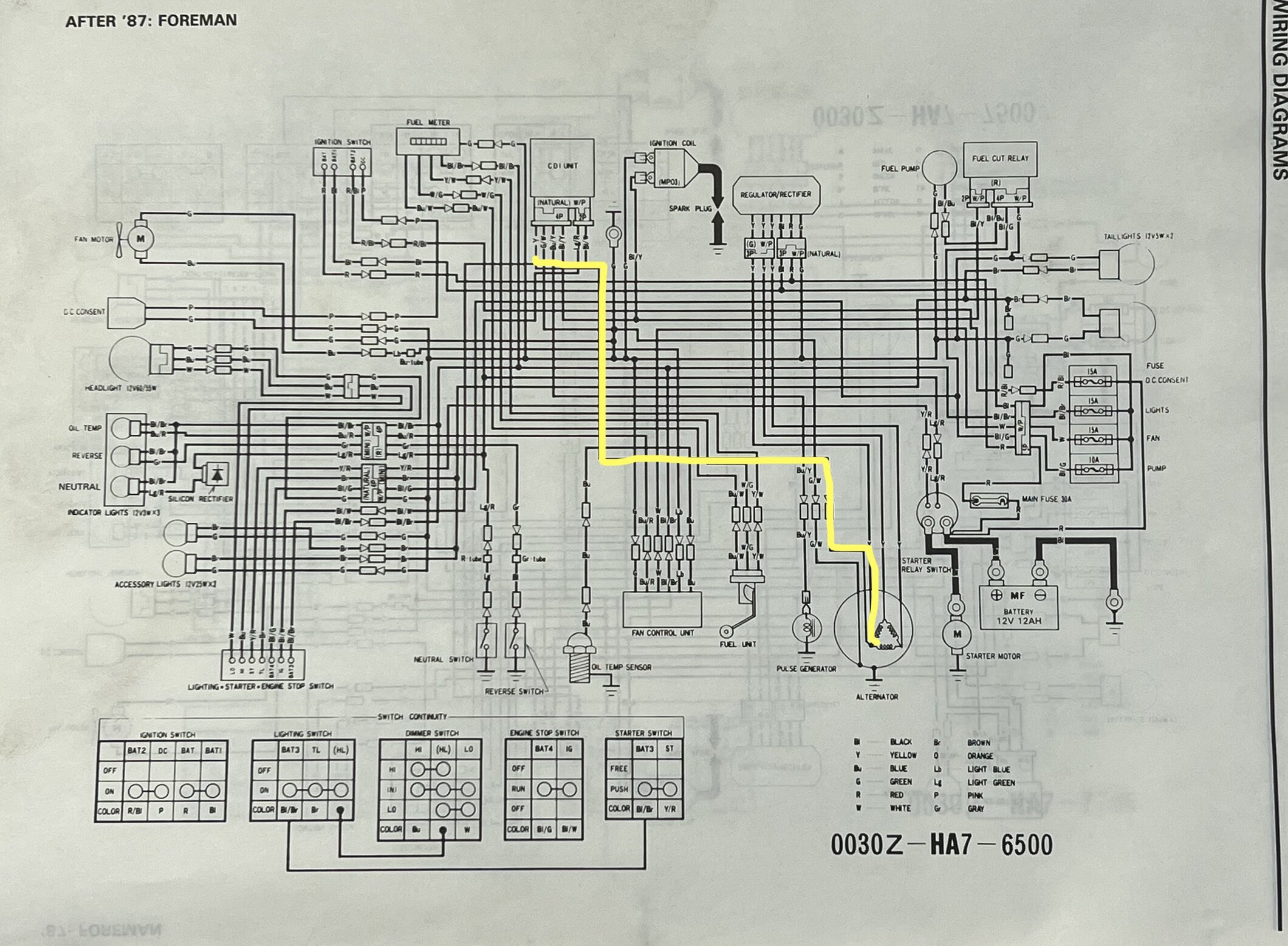
Trying to upload Schematic — not going up—you can use this to trace.
go to page 17-3
my thought is fuel system malfunction. If you’re not getting pump to come on, then see if you can jump the circuit by performing fuel flow test on page 20-8.
see the fuze block (4 + spare) and fifth fuze in a separate holder. make sure pump fuze is good by testing voltage at Black/Green wires at both the left hand multi switch and fuel cut relay. I think you’ve already successfully done this.
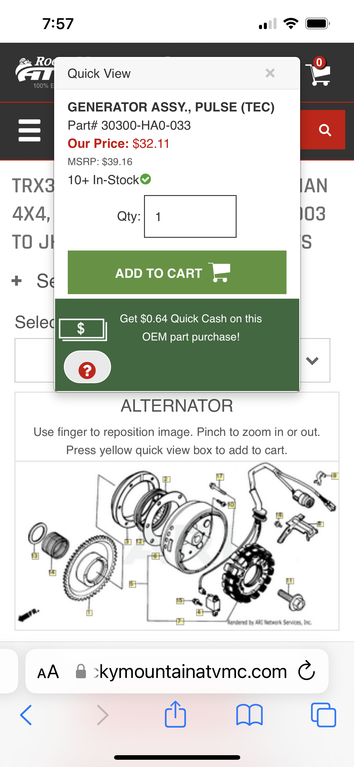
you’re talking about the pulse generator—yes these can go bad—check resistance 300-360 Ohm by testing at the connectors under the right side cover. Additionally check for continuity of the pulse generator to the CDI using the Blue/Yellow and Green/White CDi harness connectors. This should give you a complete circuit.
-
Sorry kinda late. Revolution Research Line is the 88-93 ignition system. It’s different from 86-87 TRX350A in that it does not have an exciter coil—or pickup coil as you referred to it.
the Foreman doesn’t have an exciter coil.My reading of the RRL indicates the CDI amplifies the spark. So let’s focus on that.
if you used a n aftermarket stator the directions might have directed you to leave the exciter coil (black/red) unplugged or it might have only come with a green (ground) and Blue/yellow wire (pulse generator).
i will copy the schematic for you tomorrow. I see you got wires all over. So just take a break from the meter and just try to understand how the system should work.Are you sure it’s a TRX350D?
-
1
-

Landscape work
in General Chat
Posted · Edited by Goober
You could always write in big letters with indelible ink, “Don’t squawk about my work, you wasn’t here to help!”