retro
-
Content Count
3,996 -
Joined
-
Last visited
-
Days Won
70
Everything posted by retro
-
I can't think of anything else to do except clean the grounds and troubleshoot it while its hot and no spark.
-
No spark, 2013 500 Foreman ES (now not fixed again)
retro replied to jeepwm69's topic in Electronics
This is a problem, it should match battery voltage. This is a problem too, the battery voltage should be above 13 volts with a tender on it. This is a bad sign too. So it looks like the battery is being drained by something, or it is junk. The 9/10s volt drop across the coil is a problem and the coil should not be getting hot while cranking. Possibly the coil has shorted primary windings or the harness grounds are loose/dirty. Check the ignition switch and the handlebar kill switch too. Try swapping PVA leads.... put the red PVA lead on the Red/black coil terminal and put the black PVA lead on the Green/yellow coil terminal and crank over the motor with the key on. Let me know those results. -
Welcome to ATVHonda!
-
In the first post you mentioned that a TPS code pops up sometimes? When does the TPS code come up, is it only after it gets warm and loses spark, or is it occurring randomly while the motor is running? Please explain.
-
No spark, 2013 500 Foreman ES (now not fixed again)
retro replied to jeepwm69's topic in Electronics
Ok then, after you check the initial voltage at the coil as described above, try checking the peak voltage at the coil while connecting the red PVA lead to the Green/yellow terminal and the black PVA lead on the Red/black terminal. Let me know those results. -
No spark, 2013 500 Foreman ES (now not fixed again)
retro replied to jeepwm69's topic in Electronics
2013 Foreman might have seen a major change in the ignition circuit ECM/PCM, as the 420 Ranchers wiring are entirely different from the Foreman models and the 2012 Foreman wiring differs from the 2014 foreman wiring. I don't have a 2013 diagram for reference, so lets try something, see if we can find out which manual to use for reference.... Using your multimeter, key turned on, measure DC volts with the red meter lead on the coil Green/yellow terminal and the black meter lead on the Red/black terminal. Is there positive (+) battery voltage? If so what is the measurement? Then swap your meter leads so the red lead is on the Red/black coil terminal and black lead is on the Green/yellow terminal. Is there positive (+) battery voltage? If so what is the measurement? -
No spark, 2013 500 Foreman ES (now not fixed again)
retro replied to jeepwm69's topic in Electronics
The battery is low, should be 12.6 volts or higher. The 7/10s of a volt drop (from 12.41 across the battery) at the Red/Black coil terminal is a problem though. Check fuse sockets for overheating and unplug/plug back in harness connectors in case there is a bad connection. Also check the handlebar kill switch, there should be battery voltage coming out of it.... it's a black/white wire if i remember right. The grounds are good right? -
I don't see how an oil temp sensor could cause loss of ignition. It behaves like the primary winding in the coil is shorted (coil overheating). So clean all grounds first, including the harness-to-frame ground (important!). Then when it gets warm and loses spark walk through diags until the failure is found. Start with the coil. When it loses spark measure for battery voltage on the Red/Black wire (other multimeter lead on frame ground) plugged in to the coil. Then check peak voltage on the Yellow/Green terminal on the coil, then check the CKP peak voltage at the ECU connector.
-
No spark, 2013 500 Foreman ES (now not fixed again)
retro replied to jeepwm69's topic in Electronics
I'm not buying that... I don't trust the manuals either because there is conflicting info (error) between the two that I am using. So lets back up a bit and ignore the manuals for now... Does the fuel pump run when you turn the key on? With the coil plugged in and the ignition switch on, using your multimeter measure DC volts between the Red/Black coil terminal and ground. There should be battery voltage (12.5v or greater). Then move your Red multimeter lead from the Red/Black terminal to the Green/Yellow terminal on the coil and measure again (black meter lead on ground). Let me know if you measure any voltage. EDIT: FYI, I am using the 2012 Foreman and the 2014-2016 Foreman manuals. I don't trust either of them. EDIT 2: I am helping my daughter babysit for two babies, nightmare babies actually. I'll try to check in often but if I'm awol for a while that just means I'm preparing a rocket for a low orbit launch..... be back asap. -
No spark, 2013 500 Foreman ES (now not fixed again)
retro replied to jeepwm69's topic in Electronics
Yep the CKP sensor peak voltage is good all the way to the ECU. With the coil plugged in there is not 100v or more peak voltage while cranking though, so it possibly has a bad PCM/ECU? I'll have to study the wiring a bit... -
You'll need to perform this ES prep completely. You might have a seized or crooked reduction gear support bearing.... You'll need to shine up the motor and frame grounds as well as dielectric grease every harness connector, so both the front and rear fenders must be removed. https://atvhonda.com/topic/570-how-to-properly-prep-your-honda-es-shift-system/
-
Yeah you can bypass the power steering and jumper to the ECU to rule out the PS RPM detection. I suspect that component diags will have to be done while it's hot and has lost spark though. Which means that it's gonna take more time than it normally might. It is behaving like the ignition coil primary winding is shorted. Or it could be a poor ground somewhere... I'd shine every one of those up before starting hot diags.
-
Yeah it was a lot more work but if I remember right I felt that the mounting plate was too long for the bike. If I would have just bolted the plate onto the frame as the factory intended then the fairlead would have protruded out in front of the bumper a lot further, which looked china in my opinion. Another reason is that I tend to disassemble, modify and optimize everything that I build.... it's just work after all -- and optimizing things is something that I've always been good at. When I was a 6 year old kid I thought that I wanted to become a mechanical engineer.... I changed my mind as I grew older because re-tinkering everything else (as well as mechanical things) was more fun than just being a one-trick-pony. Honestly I just never grew up.... I think you'll have to mod a KFI to get it to fit good and look good on a 350 Rancher. The aftermarket has been dominated by china for decades so almost everything has been junk since the mid-1970s. Maybe another brand of mount will fit good, but maybe not.
-
This is the mount that I put on my '00 Rancher and likely it's the same part number you're looking at? https://www.kfiproducts.com/100505-honda-rancher-350/400-winch-mount.html As I said I modded the plate a bunch by cutting away a portion of the plate where it comes close to the row of harness connectors and I cut off the two brackets on each side of the plate then welded my own homemade creations back on so I could slide the plate up higher on the frame tubes. I don't remember whether I had to bend the Fairlead bracket to straighten it up square to the bumper or not.... maybe I did and forgot about that? I imagine a lil' customizing might be necessary on the KFI mount in order to get a good fit that you like. Here you can see how I notched the plate so it wouldn't interfere with the row of harness connectors attached to the frame. After removing metal between the mounting clamp holes on each side of the plate at the top I was able to slide the plate up higher on the frame tubes than was intended by the factory design. You can also see the two homemade brackets that I welded back onto each side of the plate near the middle of it, since those two mounting bolt locations had to be moved after the plate was slip up higher on the frame. And this is the factory stock pic. My mount looked just like this one before I hacked on it.
-
No spark, 2013 500 Foreman ES (now not fixed again)
retro replied to jeepwm69's topic in Electronics
Correct that.... coil voltage should be 12.5+ battery voltage on the Black/Red wire terminal. The voltage on the Yellow/Green terminal of the coil will be less than battery voltage due to resistance in the windings of the coil. So your 10+ volts at rest measurement may be normal...? Anyway, if there is no measured voltage peaks over 100 volts DC between the Yellow/Green and frame ground then the pulse generator/ckp tests are due up next. -
What do you use to polish your plastics? Do you use a buffer wheel on them?
-
No spark, 2013 500 Foreman ES (now not fixed again)
retro replied to jeepwm69's topic in Electronics
Coil voltage should be 12.5+ volts with the key on, so the battery might be too low/dead. I'd charge it up or jump it with a good battery and try again. The CKP (pulse gen) tests should go like so: -
It's been a good while eh? 5 years ago I think....
-
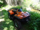
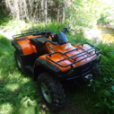
I put a KFI mount on my '00 Rancher that Jeepwm69 gave me. I didn't have any issue with the fit of the roller fairlead. I did cut the two side bolt brackets off of it and relocated them with my welder though, so I could slide the mounting plate up the frame tubes as high as possible. Here's pics of the finished mount.
-
Poor grounds can cause intermittent loss of Ignition so I'd remove and clean up all of those before trying a regulator/rectifier swap. There is the negative battery cable where it bolts to the motor, a ground cable between the motor and the frame and a wiring harness bundle to frame ground. All of them are bolted down so they're easy to shine up once ya get plastics out of the way.
-
OK, thanks for the info! The Black/White wire terminal inside the CDI connector should have positive battery voltage while the Ignition switch is turned on and the Start/Stop switch is in the Run position. The Green/White wire terminal inside the CDI connector should be frame ground. So if you do not measure any DC volts between the Black/White and Green/White terminals while the ignition key is on and the kill switch is in the Run position then it's most likely a faulty handlebar Start/Stop switch. Since your handlebar Switches Assembly is a china fake then an OEM Honda replacement part should fix it. That is.... assuming that there are no blown fuses in the fuse box. Fake china parts are garbage. They never work for more than a few minutes, and rarely ever work even for a second. China fakes fry other expensive parts often so don't ever buy that garbage again.... Let us know how it runs tomorrow after you swap on the genuine Honda switches. And Welcome to ATVHonda!
-
Tell us what you are working on, year & model. What is the issue? Have any parts been replaced? Are all parts on the ATV genuine Honda parts? Is the wiring harnesses in good condition with no splices, rodent damage or other damage?
-
Is the battery healthy? Does the starter crank the motor over at normal speed? What is the full model number and the country (USA, Canada, UK, Australia, Sweden) of origin?
-
Did you replace the carb with OEM? Aftermarket (china knockoffs) parts do not work on Honda ATVs.
-
No spark, 2013 500 Foreman ES (now not fixed again)
retro replied to jeepwm69's topic in Electronics
Aye nah... it's not quite jeep proof'd, it just did not come with any instructions, haha! The button is a momentary switch. It's function and purpose is to drain captured peak voltage from the storage capacitor inside after every test.... it resets the voltage measurement to 0 volts DC so you can repeat PV tests immediately and repeatedly.... rather than wait for the capacitor to drain on it's own. Just make sure that you disconnect one of the PVA leads from the Ignition coil before you depress the reset button, because the coil has battery voltage across it while the Ignition switch is turned on... if you press the reset button while battery voltage is present you might (or might not) let all of the magic smoke out of it, depending on whether I took that sort of usage case into consideration when I put the PVA together? I don't remember.... so to be safe disconnect the lead from the coil before pushing the button. There is no initial battery voltage present across the Crank position/Pulse generator so you can leave the leads connected while resetting for another test in those cases. By the way, all credits belong to @Melatv, that homemade PVA was made to match his DIY circuit that he posted either here, or possibly on the old VS forum? If I put it together right it should work great. EDIT: Here are the links to @Melatv's DIY PVA threads: https://www.hondaatvforums.net/threads/make-your-own-test-adapters.120450/ https://www.hondaatvforums.net/threads/peak-voltage-adapter.34406/