
retro
-
Content Count
4,007 -
Joined
-
Last visited
-
Days Won
70
Posts posted by retro
-
-
2 hours ago, jeepwm69 said:To clarify, when I measured at the coil, that was with the ECU plugged back in. I think with the ECU unplugged I would get no voltage at the coil, correct?
Even with the ECM gray connector unplugged there should be battery voltage at the coil, fuel injector, display meter, DLC connector, ECM gray connector, ignition switch, etc. since all of those Bl/R wires are fed battery voltage at the JC 2 junction connector. Hopefully the issue is as easy to trace down as it logically sounds.

-
6 hours ago, jeepwm69 said:12.7 V at battery now. I’ve had it on a tender.
I unplugged the gray connector on the ECU and checked the black/red wire going to ECU.
12.7vthen I checked the black red wire at the coil which is supposed to come off of that same black and red wire going into the ECU and got 11.5 V
It looks like a wiring issue to me, since you had the gray connector unplugged from the ECU and still measured a 1 volt drop at the Bl/R coil terminal.
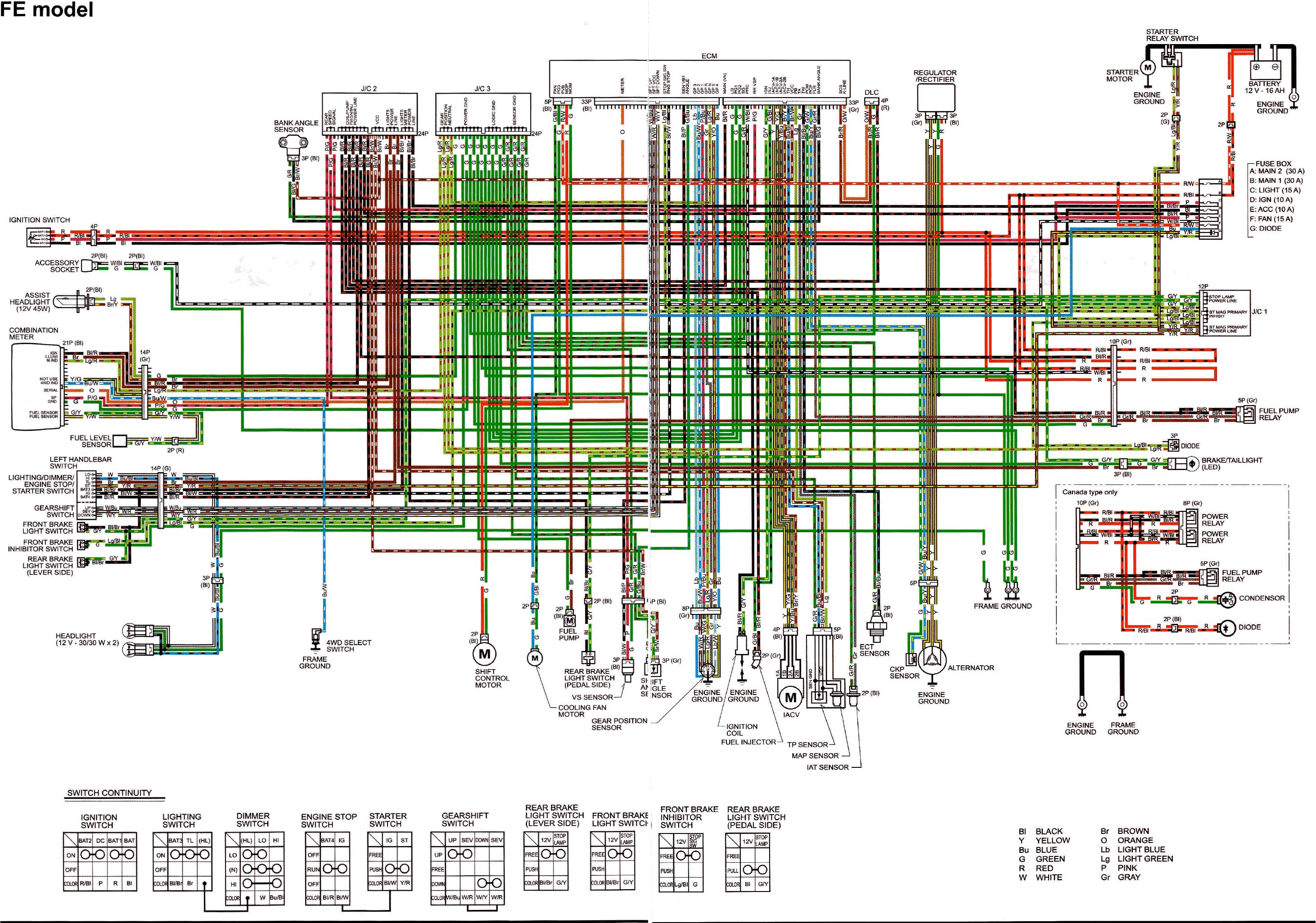
Check out the wiring diagram below.... trace the coil Bl/R wire and notice it joins the Fuel injector Bl/R wire inside the wiring harness. Then that Bl/R wire continues to J/C 2 junction connector where it is joined with fuel pump Bl/R, power Bl/R, DLC Bl/R, ECM Bl/R etc.
Unplug and check voltage at the Fuel injector, in case the issue is the internal harness junction where the coil BL/R joins the Fuel injector BL/R. I'd put my money on that internal harness crimp joint at this point.... but if the Fuel injector Bl/R measures the same voltage drop as the coil Bl/R, then check voltage on all of the BL/R wires inside the junction connector if you can.
I am working on a major bathroom demo & enlarge/replace project for my daughter so I can't be here very often, but I'll try to check back here at least once a day. Have fun tracing!

-
Yeah it looks like there is a possible current drain somewhere in the ignition circuit. If battery voltage goes through the Ignition switch before reaching the 10 amp fuse (as the diagram shows) then the drain is downstream from the ignition switch and the 10 amp fuse.
-
Yeah you can go ahead and check the Ignition switch. Let me know how that goes.
-
Use a stock NGK spark plug. It sounds like your float valve is leaking causing it to flood. The Shindy kit for your '87 TRX350D is #03-023 according to Shindy. Jeep beat me to it....
https://www.shindypro.com/product-page/carburetor-repair-kits
A Shindy kit should fix it unless your fuel pump isn't shutting off. You can test that by plugging the fuel hose and turn the key on. The pump should run briefly then shut down at about 5 PSI or so.
-
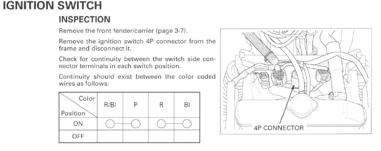
Yeah there are two pairs of wires, Red/black and pink is one pair and Red and Black is the other pair. With the key off there should be no continuity between the Red/black and pink and no continuity between the Red and Black. With the key turned on there should be continuity between the Red/black and Pink and continuity between the Red and Black. You're working inside the connector on the switch side, not the harness side.... let me know those test results.
Leave the battery disconnected for now, but go ahead and plug in your new OEM relay module and OEM coil and plug your ECM/PCM back in carefully, so everything is ready to go except for the Ignition switch and battery.
-
You guessed it.... your carb is flooding fuel after you put a china carb kit in the carb. You'll need to remove all of the All Balls carb kit parts and either put all of the original Honda OEM parts back in the carb, or replace them using a genuine Shindy carb kit.
All Balls kits are china garbage and china garbage does not ever work on a Honda.
It sounds like your fuel pump is fine. Let us know how it goes after the china parts are removed.
-
 1
1
-
-
Ok, it's been a while so I went back and read this thread from the beginning. It looks like we left off with no power to anything, the display, lights etc. all dead. So nevermind the Relay tests for now, we need to find out if the Ignition switch has failed or not.
As stated a few times earlier, DO NOT PLUG ANY CHINA PART IN AT ANY TIME. Throw them all away.
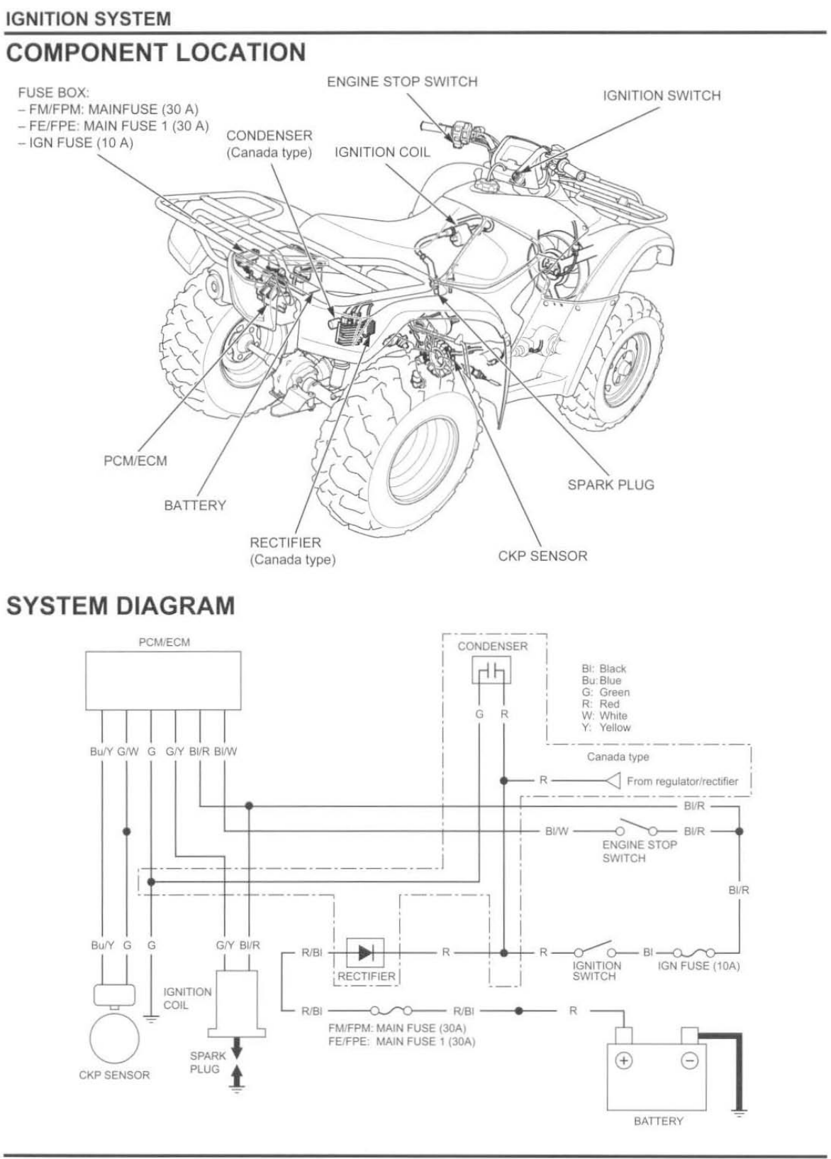
Remove the front rack and the front fender and find the Ignition switch 4p connector and unclip it from the frame. Put your multimeter in Continuity mode or Resistance mode and check continuity at the switch-side of the connector on the two wire color pairs as shown in this diagram. Test with the Ignition switch turned Off and then test again with the switch turned ON. Report those results.
-
You can disconnect the positive battery cable and set your multimeter up to measure amps current with the red meter lead on the positive battery post and the black meter lead on the positive battery cable. If there is any current with the key off, unplug (& plug back in) component connectors one at a time until you find the culprit. Note that the display meter may draw a milliamp or so while the key is off - thats normal.
-
 1
1
-
-
What year is it? Is the oil clean and the oil level right on the money?
-
1
-
-
I can't think of anything else to do except clean the grounds and troubleshoot it while its hot and no spark.
-
3 hours ago, jeepwm69 said:11.24
This is a problem, it should match battery voltage.
3 hours ago, jeepwm69 said:Battery is still at 12.31 V and I’ve had it connected to a tender
This is a problem too, the battery voltage should be above 13 volts with a tender on it.
3 hours ago, jeepwm69 said:Coil is hot to the touch after I tried to crank it
This is a bad sign too.
So it looks like the battery is being drained by something, or it is junk. The 9/10s volt drop across the coil is a problem and the coil should not be getting hot while cranking. Possibly the coil has shorted primary windings or the harness grounds are loose/dirty. Check the ignition switch and the handlebar kill switch too.
3 hours ago, jeepwm69 said:It started off at like -.8 and it has been dropping the longer it’s connected to where it is now down to -.15 and still dropping, but the drop off rate has slowed the longer it is connected
Almost stopped at -.13
Try swapping PVA leads.... put the red PVA lead on the Red/black coil terminal and put the black PVA lead on the Green/yellow coil terminal and crank over the motor with the key on. Let me know those results.
-
Welcome to ATVHonda!
-
1
-
-
In the first post you mentioned that a TPS code pops up sometimes? When does the TPS code come up, is it only after it gets warm and loses spark, or is it occurring randomly while the motor is running? Please explain.
-
Ok then, after you check the initial voltage at the coil as described above, try checking the peak voltage at the coil while connecting the red PVA lead to the Green/yellow terminal and the black PVA lead on the Red/black terminal. Let me know those results.
-
1
-
-
2013 Foreman might have seen a major change in the ignition circuit ECM/PCM, as the 420 Ranchers wiring are entirely different from the Foreman models and the 2012 Foreman wiring differs from the 2014 foreman wiring. I don't have a 2013 diagram for reference, so lets try something, see if we can find out which manual to use for reference....
Using your multimeter, key turned on, measure DC volts with the red meter lead on the coil Green/yellow terminal and the black meter lead on the Red/black terminal. Is there positive (+) battery voltage? If so what is the measurement?
Then swap your meter leads so the red lead is on the Red/black coil terminal and black lead is on the Green/yellow terminal. Is there positive (+) battery voltage? If so what is the measurement?
-
5 hours ago, jeepwm69 said:Battery shows 11.7 V at the coil, 12.41 V directly off the battery
The battery is low, should be 12.6 volts or higher. The 7/10s of a volt drop (from 12.41 across the battery) at the Red/Black coil terminal is a problem though. Check fuse sockets for overheating and unplug/plug back in harness connectors in case there is a bad connection. Also check the handlebar kill switch, there should be battery voltage coming out of it.... it's a black/white wire if i remember right. The grounds are good right?
-
1
-
-
I don't see how an oil temp sensor could cause loss of ignition. It behaves like the primary winding in the coil is shorted (coil overheating). So clean all grounds first, including the harness-to-frame ground (important!). Then when it gets warm and loses spark walk through diags until the failure is found. Start with the coil. When it loses spark measure for battery voltage on the Red/Black wire (other multimeter lead on frame ground) plugged in to the coil. Then check peak voltage on the Yellow/Green terminal on the coil, then check the CKP peak voltage at the ECU connector.
-
2 hours ago, jeepwm69 said:i’m wondering if that fried that ECU
I'm not buying that... I don't trust the manuals either because there is conflicting info (error) between the two that I am using. So lets back up a bit and ignore the manuals for now...
Does the fuel pump run when you turn the key on?
With the coil plugged in and the ignition switch on, using your multimeter measure DC volts between the Red/Black coil terminal and ground. There should be battery voltage (12.5v or greater).
Then move your Red multimeter lead from the Red/Black terminal to the Green/Yellow terminal on the coil and measure again (black meter lead on ground). Let me know if you measure any voltage.
EDIT: FYI, I am using the 2012 Foreman and the 2014-2016 Foreman manuals. I don't trust either of them.
EDIT 2: I am helping my daughter babysit for two babies, nightmare babies actually. I'll try to check in often but if I'm awol for a while that just means I'm preparing a rocket for a low orbit launch..... be back asap.
-
Yep the CKP sensor peak voltage is good all the way to the ECU. With the coil plugged in there is not 100v or more peak voltage while cranking though, so it possibly has a bad PCM/ECU? I'll have to study the wiring a bit...
-
You'll need to perform this ES prep completely. You might have a seized or crooked reduction gear support bearing.... You'll need to shine up the motor and frame grounds as well as dielectric grease every harness connector, so both the front and rear fenders must be removed.
https://atvhonda.com/topic/570-how-to-properly-prep-your-honda-es-shift-system/
-
1
-
-
Yeah you can bypass the power steering and jumper to the ECU to rule out the PS RPM detection. I suspect that component diags will have to be done while it's hot and has lost spark though. Which means that it's gonna take more time than it normally might.
It is behaving like the ignition coil primary winding is shorted. Or it could be a poor ground somewhere... I'd shine every one of those up before starting hot diags.
-
1 hour ago, bigcountry78 said:I’m curious, why did you want to push it back towards the harness? Seems like a good bit of extra work for a small gain
Yeah it was a lot more work but if I remember right I felt that the mounting plate was too long for the bike. If I would have just bolted the plate onto the frame as the factory intended then the fairlead would have protruded out in front of the bumper a lot further, which looked china in my opinion.
Another reason is that I tend to disassemble, modify and optimize everything that I build.... it's just work after all -- and optimizing things is something that I've always been good at. When I was a 6 year old kid I thought that I wanted to become a mechanical engineer.... I changed my mind as I grew older because re-tinkering everything else (as well as mechanical things) was more fun than just being a one-trick-pony. Honestly I just never grew up....
I think you'll have to mod a KFI to get it to fit good and look good on a 350 Rancher. The aftermarket has been dominated by china for decades so almost everything has been junk since the mid-1970s. Maybe another brand of mount will fit good, but maybe not.
-
1
-
-
This is the mount that I put on my '00 Rancher and likely it's the same part number you're looking at?
https://www.kfiproducts.com/100505-honda-rancher-350/400-winch-mount.html
As I said I modded the plate a bunch by cutting away a portion of the plate where it comes close to the row of harness connectors and I cut off the two brackets on each side of the plate then welded my own homemade creations back on so I could slide the plate up higher on the frame tubes. I don't remember whether I had to bend the Fairlead bracket to straighten it up square to the bumper or not.... maybe I did and forgot about that?
I imagine a lil' customizing might be necessary on the KFI mount in order to get a good fit that you like.
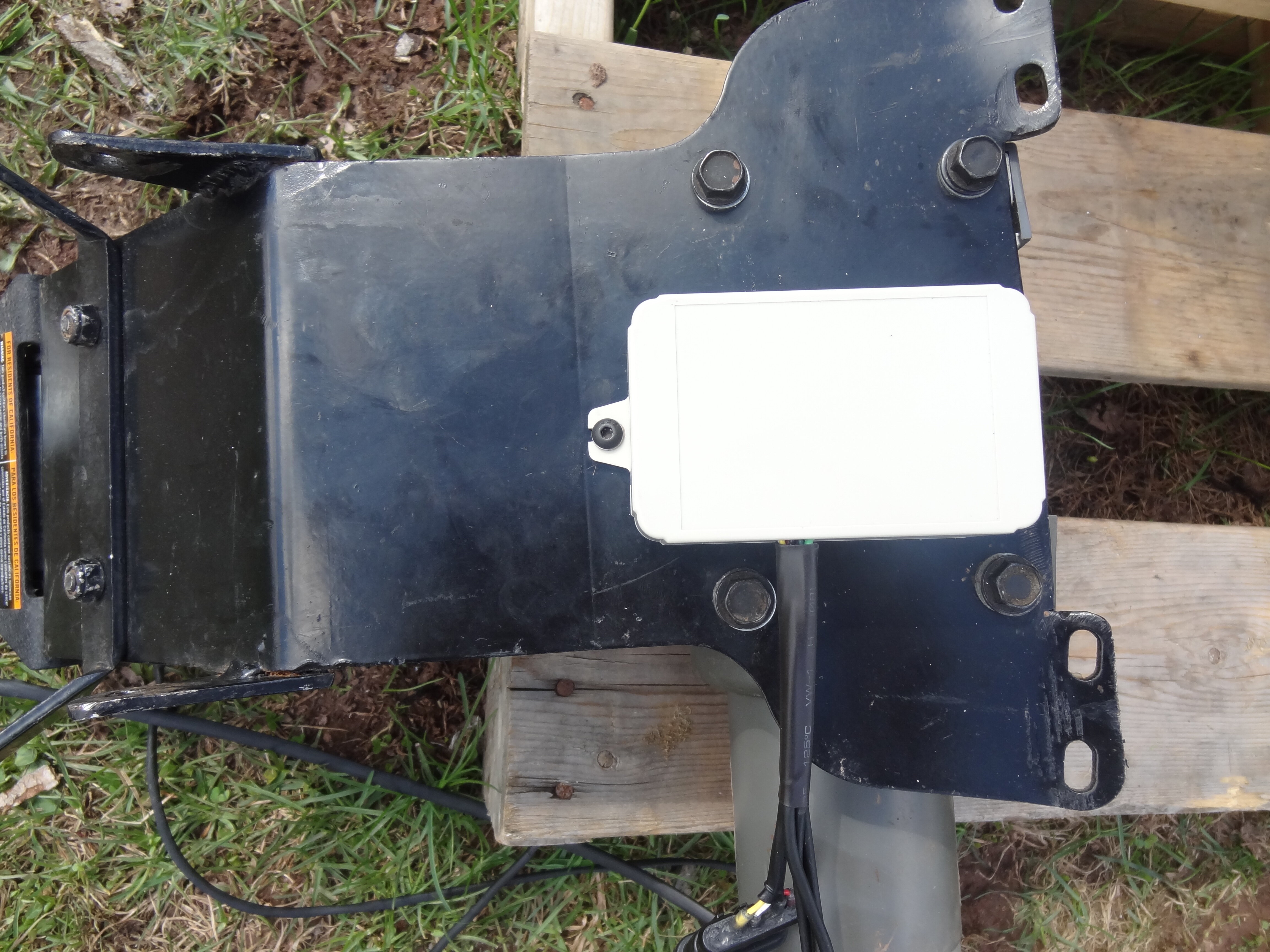
Here you can see how I notched the plate so it wouldn't interfere with the row of harness connectors attached to the frame. After removing metal between the mounting clamp holes on each side of the plate at the top I was able to slide the plate up higher on the frame tubes than was intended by the factory design. You can also see the two homemade brackets that I welded back onto each side of the plate near the middle of it, since those two mounting bolt locations had to be moved after the plate was slip up higher on the frame.
And this is the factory stock pic. My mount looked just like this one before I hacked on it.

No spark, 2013 500 Foreman ES (now not fixed again)
in Electronics
Posted
Yeah it sounds like the coil windings are shorted. The manual does not list resistance specs for the coil so the only way to know for sure is plug another coil in.