
retro
-
Content Count
4,007 -
Joined
-
Last visited
-
Days Won
70
Posts posted by retro
-
-
Why did you put a ES shift bypass kit on it? Were the symptoms the same before you plugged in the ES bypass? Please explain.
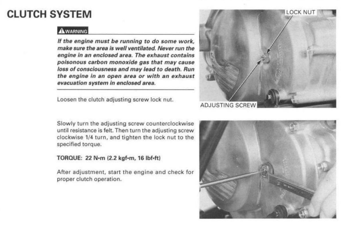
Here is the clutch adjustment instructions from the service manual, you'll need to adjust the clutch after you follow the ES prep guide completely AND return the ES system to stock.

You haven't properly prepped it yet, so you can't expect the ES to work...... wash out the old hardened white grease and make sure that the reduction gears are not rubbing on the case or cover and make sure that the tiny support bearings are not cocked in their bores. Use synthetic grease liberally.... pack the support bearings full of grease and coat the gears & gear teeth good and thick. Everything is in the guide....
Keep us posted and have fun!
-
 2
2
-
-
3 hours ago, Freedomflyer said:Colder in Bozeman
Oh my that's nasty! Stay warm!
-
8 hours ago, Patrik said:I thing these 2 connectors are the only ones with the exact same size
That's a rotten trick eh! Glad that you got it fixed! Make sure to replace those relays with OEM parts to avoid certain catastrophic failure soon.
@Melatv, good to see you again, thanks for jumping in, hope all is well and you're staying warm! Arctic air is forecast for ya as the next week progresses.
-
Hi Mossboss, here is a guide that if followed completely should get your stock ES shift system working again. Generally there is no need for a bypass kit, not until the shift ECM fails. Even then it's always wiser to fix the ES right.
Make sure that you put all of the original Honda parts (including the OEM angle sensor - aftermarket parts do not work) back on your Foreman after prepping according to the guide. Let us know how it goes.
Have fun!
-
1
-
-
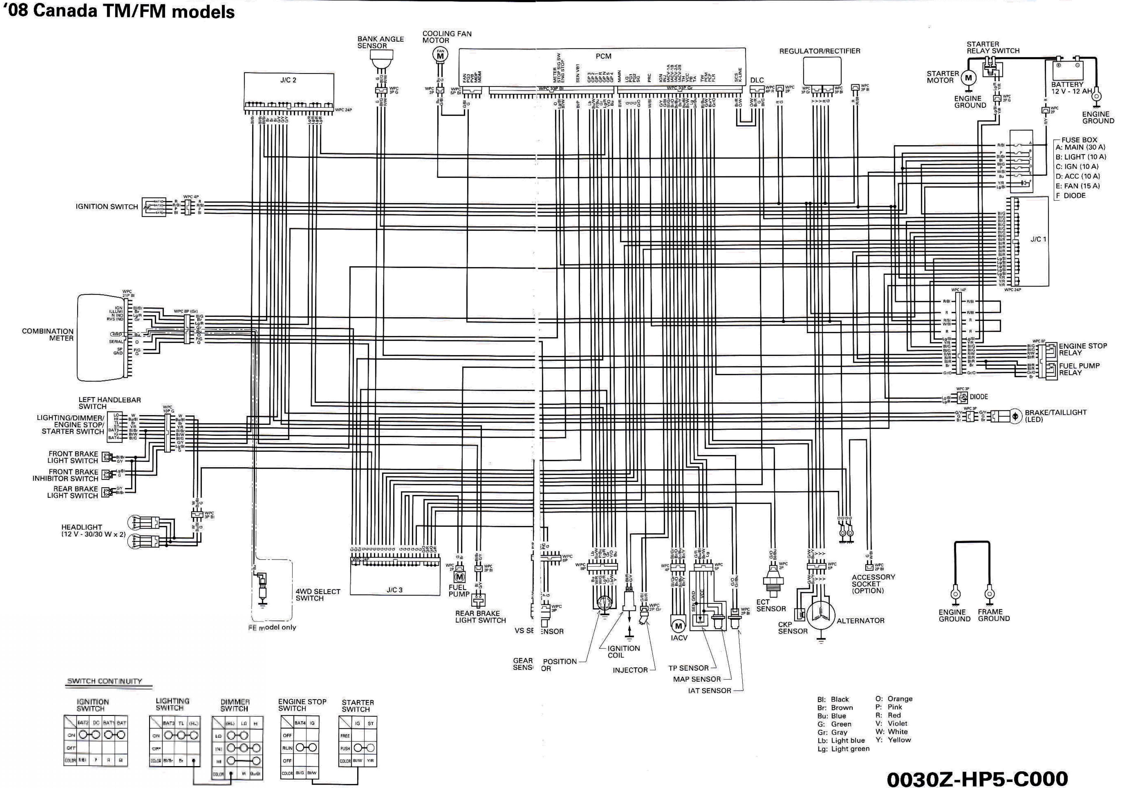
2 hours ago, Patrik said:Maybe a stupid question but where does the power goes from R/B to R? The blue circle in the picture
There are no stupid questions!

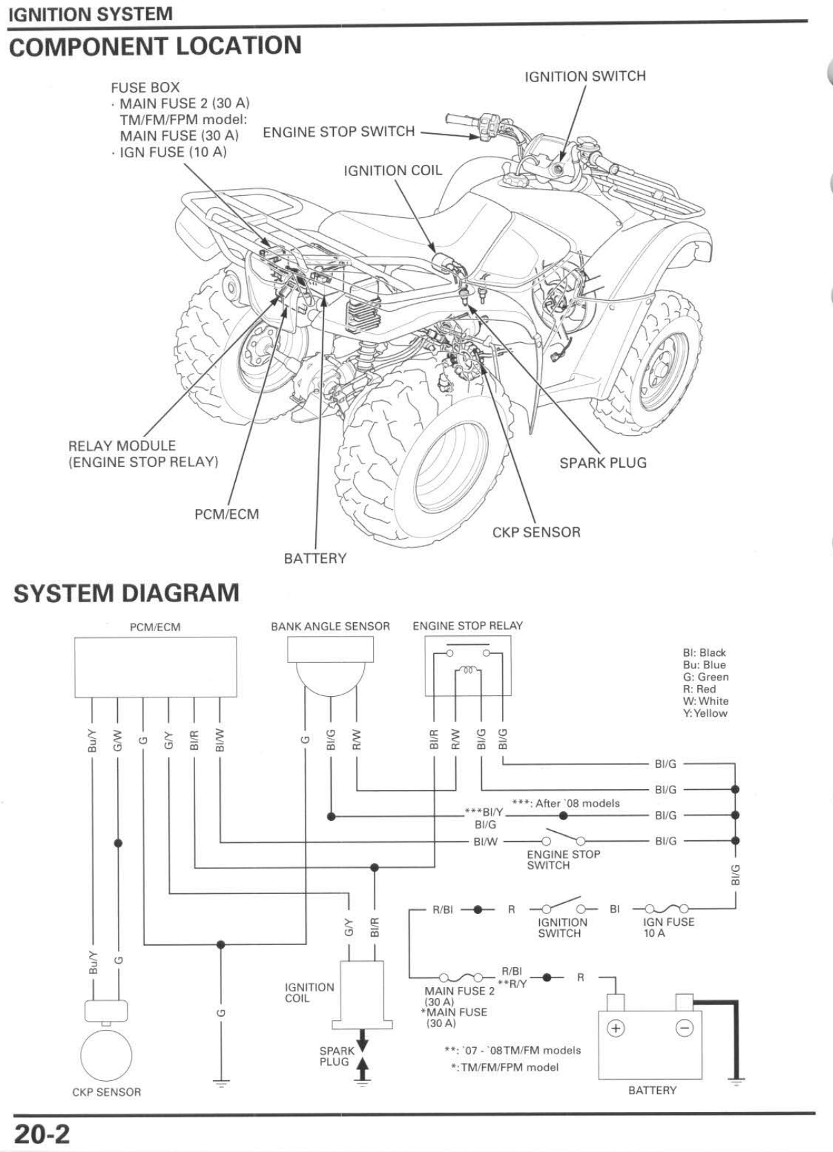
Here is the wiring diagram for the Canadian version of the '08 TM/FM Rancher 420:
In this wiring diagram there is a 14p connector that serves two functions: One function is a Waterproof junction where the Red/Black wire going in to the junction becomes a Red wire coming out of that junction. This diagram may be different from your version since this one shows the Engine Stop relay and the Fuel Pump relay unified as a single relays module, whereas your version has two separate relays. But somewhere nearby the two relays on your Rancher there should be a junction connector, OR the wire junctions may be included in your two relay connectors? Look for the relevant wire colors that could identify those wire junctions (R/Bl, R, W/Bl) going into and coming out of that/those connector(s).
If I were you I would not plug those two aftermarket relays in again. Test your two OEM relays, they are probably both good. China relays are known to stick and fry other expensive components, often immediately after plugging them in.
17 minutes ago, Patrik said:Since I don't have power in the red wire to key ignition and its connected to a few things along the way I have some searching to do!
Yeah hopefully you'll find the open circuit issue in the Junction connector(s).
Gotta run.... this is fun! Hang in there!
-
Hi Patrik,
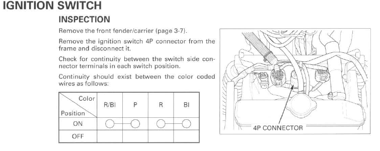
First thing you'll need to do is put all of the genuine Honda parts back on your Rancher. Then remove the front fender, unplug the ignition switch and test for continuity with the switch turned OFF then turned ON, as shown here:
I agree with @jeepwm69, it sounds to me like your Ignition switch is bad. The Ignition switch controls two positive battery voltage circuits. Make sure that both circuits are switched ON and OFF properly. You'll be checking for continuity between the Red/Black and Pink terminals and again between the Red and Black terminals inside the switch connector.
Here is the Ignition circuits diagram. As you can see positive battery voltage must pass through the Ignition switch in order to reach the 10 amps Ignition fuse.
If you need a new Ignition switch make sure that the replacement is a genuine Honda switch. China aftermarket parts are garbage and do not ever work on a Honda. China parts destroy other expensive parts, never plug any aftermarket part in.
I'll be unavailable for a few days... I'll be back as soon as I can. Let us know how it goes.
-
If I remember correctly there should be intermittent battery voltage sent through the two ignition coil terminals by the ECM/PCM...? So it makes sense that you should be able to connect a multimeter to those two coil wires with the OEM coil unplugged, turn the key on and crank the motor over and measure the Primary voltage pulses. I'm pretty sure that there should be battery voltage between the Black/Red terminal and frame ground while the ignition switch is turned ON, at least. Because if I am remembering correctly the Black/Red is hot all the time while the key is on, and so the ECM/PCM completes the ignition coil Primary circuit (momentarily each revolution of the motor - the Pulse gen signals those events) by providing ground to the Green/Yellow coil wire. If my memory is wrong holler....
I'm hoping Mach 1's ECM/PCM is still good based on the fact that it didn't go into an open-circuit condition while his coil was sizzling. His ECM/PCM continued to supply current to the frying coil until the battery completely drained. So if his stuff can take that much long-term abuse then yours should be fine.
As I said this is new territory for me, so I'm gonna learn stuff.
EDIT: If my explanation above is correct, of how the ignition coil Primary is controlled by the ECM/PCM, then the Green/Yellow wire that connects to the coil should not be providing a ground while the key is ON, and the motor is not being cranked over by the starter. So with the key turned ON you should be able to connect a test light to the positive battery terminal and touch the unplugged Green/Yellow wire terminal and the test light should NOT light up. But if you crank the motor over the test light might blink on & off (very weakly if perceptible), proving that the PCM/ECM is working.
EDIT #2: Honestly now that I've thought about my explanation above for a few more minutes, I think I have everything backwards. I think the Black/Red is hot all the time while the key is on AND I think that the Green/Yellow is grounded all the time by the ECM/PCM while the key is on. The Pulse Generator signals to the ECM/PCM to interrupt the ground that is being provided to the Green/Yellow wire, causing the Primary voltage magnetic field to collapse in the coil, which by induction the Secondary coil windings create the high voltage that jumps the spark plug gap.
Whew!
-
3 hours ago, jeepwm69 said:You think I'd be ok just putting a new 10A fuse in with the new OEM coil and trying it?
That's what I would do if I were working on it because evidence is lacking (so far) that it needs anything more. I mean, you know precisely what happened to it and why it happened..... it was supposed to happen so your fix should be routine. I would also make that Caltric regulator disappear, because if ya don't it will eventually end up plugged in again, making more unnecessary work for you. But I'm sure that you have a plan for that already, so....
Your case differs from Mach 1's Rancher in that the china barbecue was brief and terminated the moment you turned the ignition switch off. We got no reason to suspect that anything besides the coil fried, so far....
While in his case the china relay module stuck closed while the smoke was let out, so his barbecue continued long after he turned the ignition switch off -- until the battery was drained completely dead. So I have concerns for his stuff where I don't for yours. If the ignition switch survived on his Rancher then the next step will be to plug OEM parts in and find out.

-
1
-
-
Congrats and thanks for sharing your experience with us!
-
On 1/2/2024 at 11:57 AM, jeepwm69 said:@retro, safe to say I should do the same with this 2013 Foreman I picked up yesterday?
Yeah, maybe check that the high current coil barbecue didn't take out the ignition switch? I'd guess that's optional though, it's probably fine. Other than that, since your relay module is OEM a 10 amp ignition fuse is probably all you should need.
I have never dealt with a shorted/fried china ignition coil on a PGM-FI fuel injected Rancher/Foreman, so I don't know what to expect.... I'm a bit concerned about the ECM/PCM, since all of the short circuited current flowed through it.
-
Your IN/OUT winch switch and contactor relay (if equipped - some old Warn winch installations did not include a contactor, but had a high current capacity rotary switch on the handlebar) should be connected into a switchable, fused circuit such as the accessory circuit, which is provided for add-on purposes. Check your add-ons..... you left a clue that your winch may be wired up incorrectly, directly to battery positive....? While the ignition switch is turned OFF the winch should not operate.
-
Another common issue I see quite often is hacked up wiring harnesses and add-on accessories that are wired into the harnesses on the wrong power supply circuits, and I often just find wires stripped bare and twisted together and taped up with electrical tape. I work on a lot of Honda's that are owned by cattle ranchers. Most of them are cobble-job artists who have no business working on their own equipment. So if you are not the original owner of your Foreman, it'd be a good practice to go over your harnesses and fix any connections that are cobbled or connected into the wrong circuit (check your winch wiring or add-ons if ya got any). All add-on wiring connections should be soldered and waterproof sealed up.
40 minutes ago, trailcutter said:i asked about the diode and you said it wasnt related to my issue.
Right, an open or shorted diode has nothing to do with how the motor runs, it only functions the moment you release the starter button.
You can check the diode after you remove it from the fuse box by setting your multimeter to Continuity mode, or Resistance mode. Then touch each of the two diode terminals with your two multimeter leads and note whether the diode conducts or not. Reverse the two multimeter leads on the diode terminals to note if the diode conducts or not in the opposite polarity.
A good diode should conduct current flow in one direction only.
So if your diode conducts in both polarities the diode is shorted (depending on the ATV model a shorted diode may result in a no spark - no start condition).
If it does not conduct in either polarity the diode is open circuit (which allows flyback voltage to discharge into the CDI and/or shift ECM if equipped).
Only if the diode conducts in one direction, but does not conduct in the opposite direction, is the diode a good one.
-
20 minutes ago, trailcutter said:my feelings are i had this issue before i changed the cdi that maybe damaged the oem cdi.
Three common reasons why OEM CDIs fail are:
- The Diode in the fuse box fails in an open circuit condition, which allows flyback (high) voltage to discharge into the CDI.
- Water gets into wiring harness connectors causing corrosion of the terminals - open circuit condition.
- An OEM electrical part replaced with a china part.
Speculation is generally a waste of time though, until diagnosis of failed circuits is complete.
Just now, trailcutter said:that seems strange why would the system be wired so thar engine would shut down because a lightfuse has blown,and why do i still have power to winch?
Refer to the wiring diagram.... for "why" questions. Short answer: there are two power circuits controlled by the ignition switch, not one.
-
While you are replacing china parts with OEM parts you may as well check the Ignition switch for an intermittent function issue. If the ignition switch has been replaced with china you'll have to correct that with OEM too.
-
10 minutes ago, trailcutter said:no ignition with no light fuse
Removing the light fuse disconnects battery voltage from the ignition switch. See the wiring diagram.....
-
@Mully, that is definitely a Mitsuba genuine Honda starter motor. I haven't seen that kind of wear on a Honda starter armature shaft and chipped tooth damage to the driven gear, except on the old '86-'89 TRX350 Fourtrax models. My best guess is that the driven gear tooth broke off (it is much softer metal than the armature shaft is) first, then the armature shaft got destroyed by the chipped tooth driven gear. The broken tooth is in the oil sump now, so best practice is to find it and get it out of there while you are replacing parts.
You'll need a genuine Honda replacement starter motor, you might find a used one at Powersportsnation.com that you can prepare for a long life by replacing the brushes with OEM brush kits.
-
1
-
-
If I were you I would unplug that china CDI immediately and remove it. That china junk can start a fire and burn your Foreman down, along with the building that it is parked in.
Also, if any of the other parts on your Foreman are aftermarket, you'll need to remove those as well and replace will genuine Honda parts.
We cannot help you until all of the aftermarket parts have been replaced with Honda parts. Let us know how it runs when you get it sorted out.
-
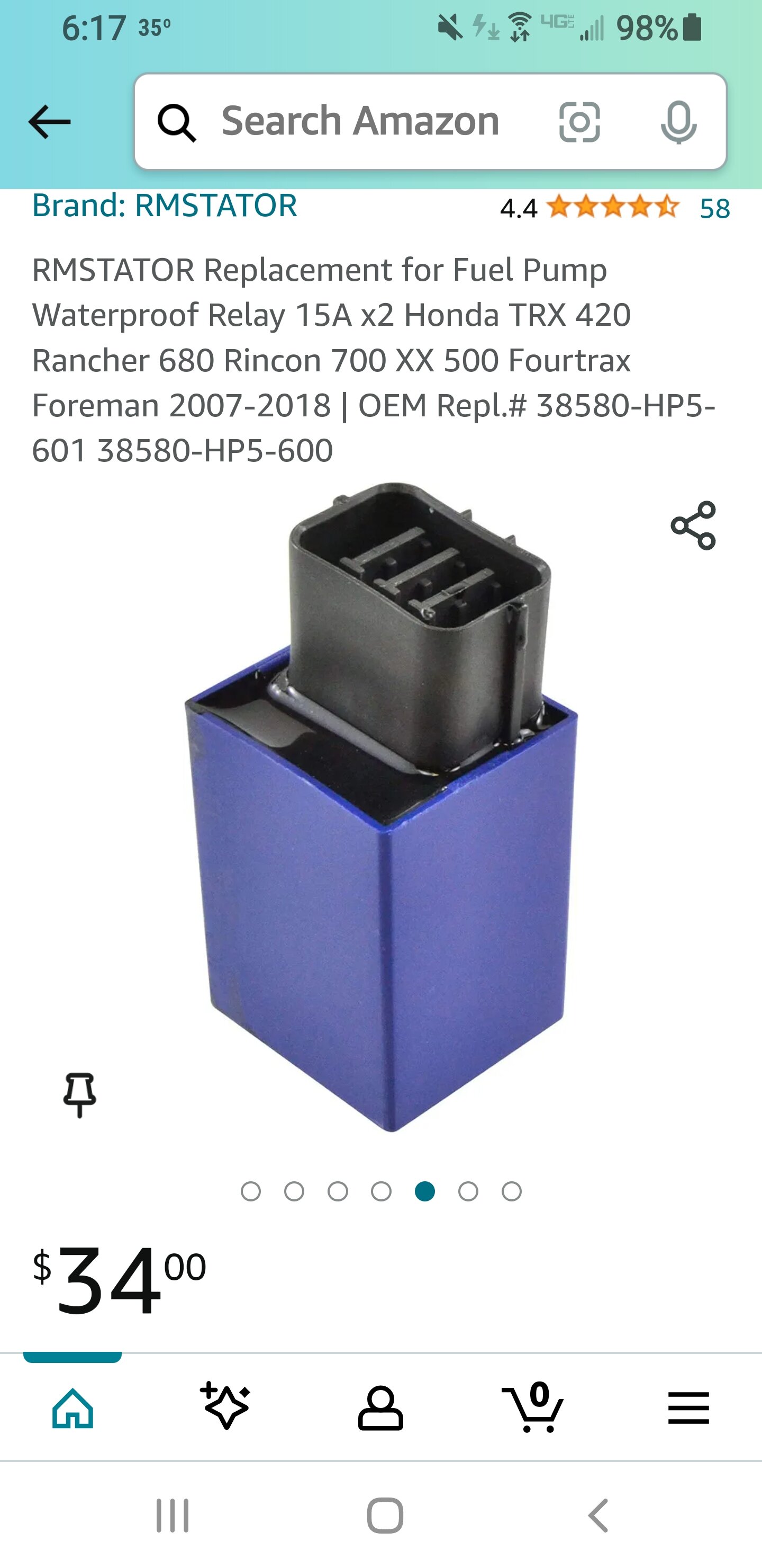
7 hours ago, Mach 1 said:Here is part I replaced along with aftermarket coil..Shop replaced IAC, which was weird since I had zero miles on one I put in, initial issue was wouldn't keep running without throttle, got it back and second ride blew fuse, died and now it sits..thanks
Yeah, that is the Engine stop/Fuel pump relay module. I gave you some test instructions concerning that relay and wiring that connects to it and then you couldn't find that relay, so I was questioning which relay you had replaced.
Nevermind those test instructions for now though, we already know that the relay module is junk, our only concern is the circuitry that connects that relay. Let's come back to that later....
Make sure that the junk ignition coil and the junk relay module are both unplugged and do not ever plug them back in.
Make sure that the battery is disconnected and stays disconnected.
Lets check the Ignition switch first, because the ignition switch was overloaded with excessive current during the short circuit events -- it might be damaged or fried.
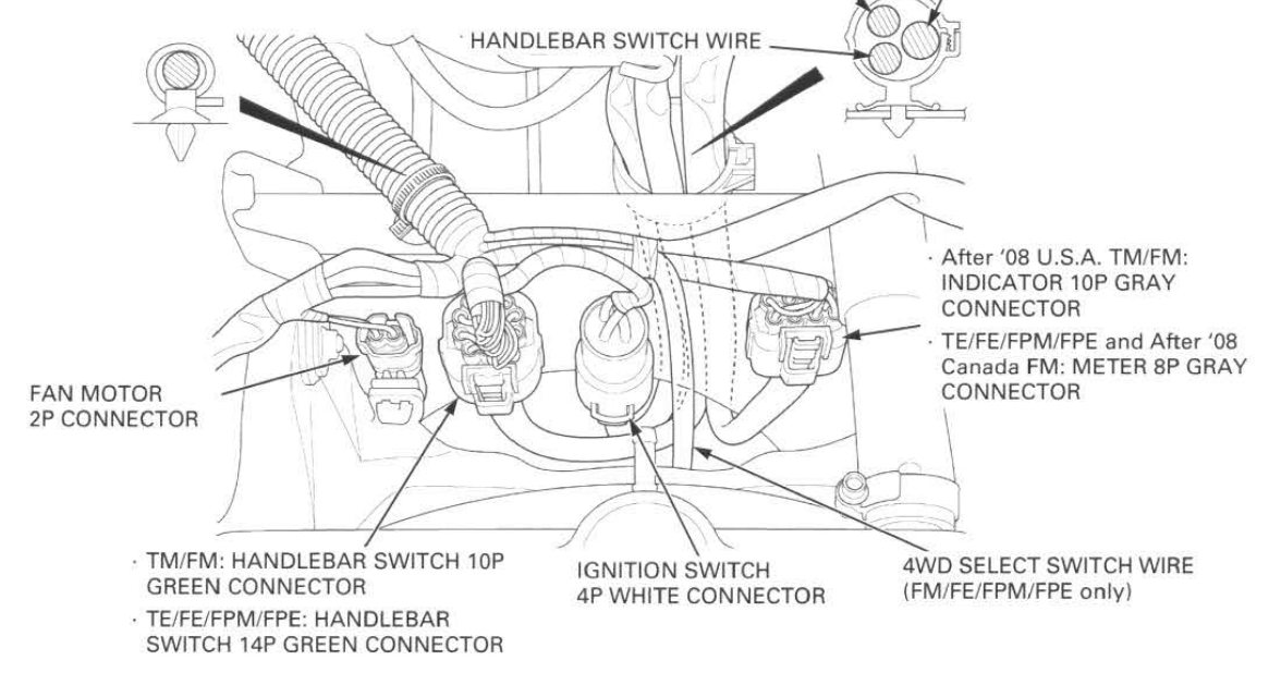
Remove the front rack and the front fender. Find the 4p connector for the ignition switch and remove that connector from the clip that attaches it to the frame and unplug that connector. See the image below for it's location.
Inside the ignition switch connector on the switch side sub-harness, with your multimeter in continuity mode, with the Ignition switch turned OFF, probe one meter lead on the Red/Black wire terminal and the other meter lead on the Pink wire terminal. There should be no continuity between those two terminals. Then probe one meter lead on the Red wire terminal and the other meter lead on the Black wire terminal. There should be no continuity between those two terminals.
Report back with those results.
Then turn the ignition switch ON and repeat those same two tests. There should be continuity for both tests this time.
Then turn the ignition switch OFF. Report back with those results.
-
My best guess is that your Foreman had a china aftermarket starter motor on it?
-
Sounds like it still has china parts on it.
-
Hi LureheadEd, welcome to the forums!
It sounds like you bought a spark plug wire (or a complete ignition coil?) and a CDI module for cheap.... first thing I need to warn ya about is to NEVER replace any genuine Honda parts with aftermarket parts. Cheap China aftermarket parts do not work on Honda's AND they sometimes fry other expensive electrical parts. DO NOT PLUG IN ANY PART that is not a genuine Honda part. Put the original Honda parts back on your Foreman if you have replaced any of them.
You may have to clean (or replace) the fuel petcock that is attached to the bottom of the fuel tank as they are made from aluminum and they sometimes corrode badly inside which can plug up the passages inside. You can test the petcock after removing it to make sure that it flows liquid (or you can blow air through it) while the valve is turned to the "On" position and "Reserve" position. The plastic filter screen on the petcock may be rotten as well, replace if it is split open or shows other signs of serious decay. If it is good just clean it carefully.
When removing the petcock from the fuel tank it helps to use an Impact gun to break the two screws loose, as sometimes the screws become seized in the brass ferrule nuts that are embedded in the plastic tank and the brass nuts loosen and spin in the plastic, which results in you not being able to remove those two screws. The shock that an Impact gun puts on the screws helps to loosen them from the brass ferrule nuts.
Let us know how it goes.
-
1
-
-
6 minutes ago, Mach 1 said:Ok, makes sense now, connector on fuel pump relay is one I should test..thanks.
Yeah, but first lets figure out which part you replaced, because it doesn't sound like the Fuel pump/Engine stop relay module.
-
The Diode is an electronics protection component. It prevents flyback voltage that is released from the Starter solenoid when the Starter button is released, from damaging sensitive electronic components such as ECMs and ECUs. Every now and then one fails but not very often. The Diode's function is unrelated to your issue.
-
I apologize @Mach 1, I have been busy and haven't been on the forums for a couple days so I missed your questions. I have a couple projects I'm working on and one of them, prepping my old Arctic Cat sled for winter, became much bigger than expected once I got it apart and found some rotten rubber boots and rotting fuel line. I only intended to remove and clean the carbs.... routine maintenance stuff. But since I found some rotten stuff I decided to go all in and fix some other things that have been needing fixing too... such as replacing the seat cover that the neighbor's kids two dogs chewed up last winter while I had left the sled at their farm for them to play on... and gonna replace the tail light on it that I broke two years ago when I got it stuck.

So I will be around the forums only occasionally for a while.
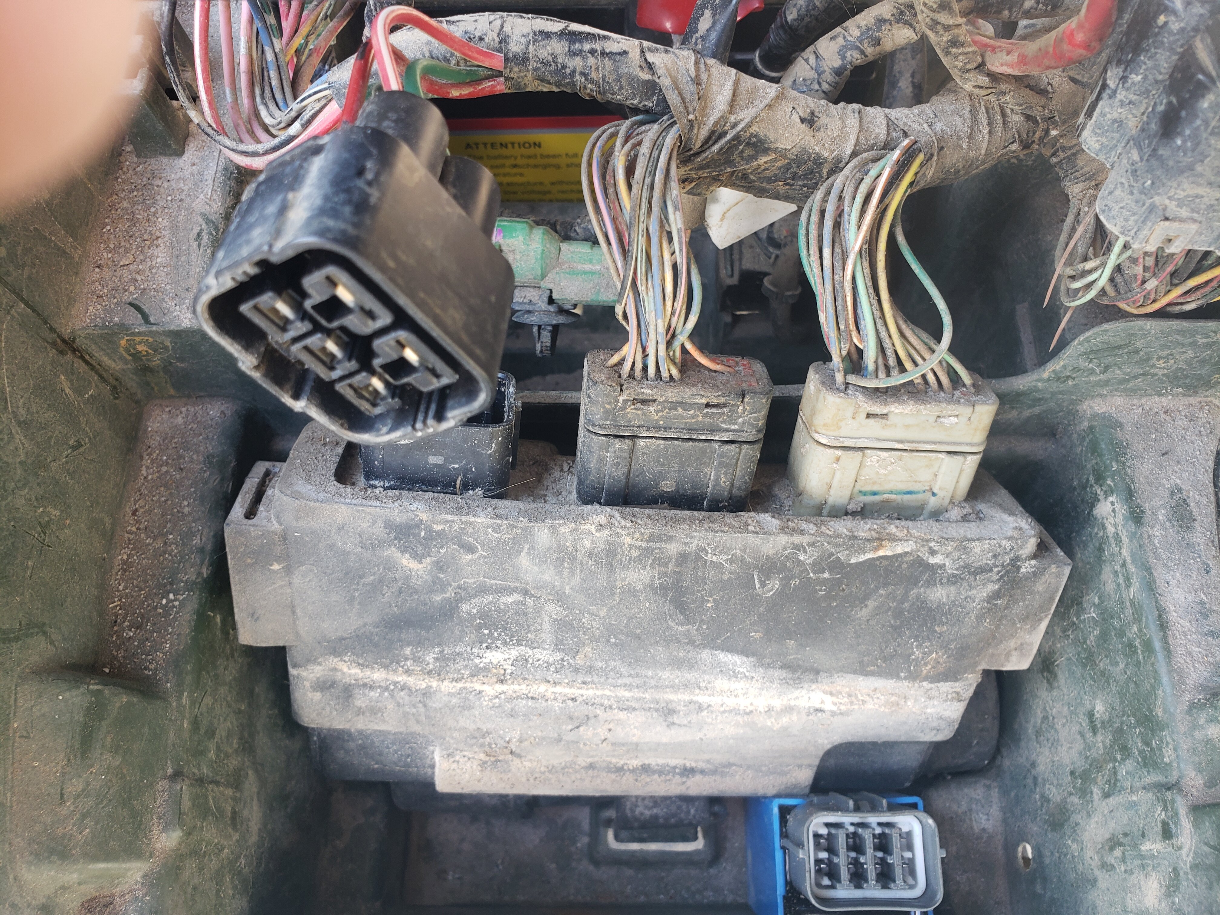
On 12/28/2023 at 12:37 PM, Mach 1 said:In this pic, is harness disconnected the stop relay??
As Jeep confirmed, that is the ECU/ECM in your photo. The Engine Stop relay is part of a module that includes the Fuel Pump relay. It has an 8p harness connector with 4 of those 8 wires controlling the Fuel Pump relay inside and the other 4 wires controlling the Engine Stop relay inside. See the image in the post above...
You said that you replaced a relay with an aftermarket part..... let's figure out what that part is Ok? Unplug that part and list the wire colors in it's harness connector so we can identify it before proceeding.
I'll be back later....

2003 450es shifting problems
in Electronics
Posted
I can sympathize with that.... I prepped my Rancher ES during the winter with 2 feet of snow already down.... no shelter. I took the parts indoors to complete the work, but I had to wash the tiny bearings in the front cover, pack them with grease and reseal the shift motor cover outdoors. I spent two days on it if I remember right.
If you have a good multimeter you can check the Angle Sensor resistance (manually shift up and hold - shift down and hold - to measure resistance) at rest and each direction of sensor rotation as the service manual instructs. Let us know if we can help.