
retro
-
Content Count
4,007 -
Joined
-
Last visited
-
Days Won
70
Posts posted by retro
-
-
Awesome @shadetree, you went off retro-like on the keyboard, leaving no questions out of the book! Your post looks like a How to bleed front brakes sticky to me.... what say we pin it up after M_goerler is done with it?
-
 2
2
-
-
China parts are all garbage, no exceptions. You'll need to replace with genuine Honda parts, then you'll be able to bleed the air out. You can buy good used OEM Honda parts from powersportsnation.com if you don't want to pay the high prices for new ones.
What is the year and model of your Honda? There are a few tricks that we can share that will help you get the air out, depends on what you're working on though. Get genuine Honda parts back on it, adjust the brakes, then let us know what ya got and we'll help ya bleed it.
-
6 hours ago, rich250rracer said:Unfortunately that is 100% incorrect. There are seven wires to this switch, one for each gear, 1-5 and one for reverse, one for neutral. By your theory, every one of these wires should be hot. None of them are. This switch takes each circuit to ground when a gear is changed. Look at the OEM service manual wiring diagram for a TRX500FPM, this switch provides ground for the circuit. It takes each position to engine ground. There is absolutely NO power to the switch.
@shadetree is 100% correct! As you now understand voltage exists and current flows through every conductor in a functional circuit, including the frame. You can measure those voltages and currents using your multimeter, or confirm them with a test light. The "hot" wire in question is the one that completes the path to negative depending on the gear selection, which means that all seven wires individually and independently become "hot" at some point while shifting through the gears.
As I mentioned earlier, any fundamental misunderstanding of how electrical circuits work will always lead to misunderstandings later on in the diagnosis processes.
Again, not intending to be a jerk, just making a correction.
-
 1
1
-
-
6 hours ago, rich250rracer said:I think I misspoke in my video. Continuity wasn’t the terminology I was looking for.
No, you were correct, you were testing the gear position switch for continuity to ground. Until you turned the key on that is..... at that point battery current flowed through your measuring device which terminated that measurement.
6 hours ago, rich250rracer said:That gear position switch isn’t hot, there is never power to it.
Yes there is.... in a functional DC circuit loop battery current flows from the positive plates in the battery until that current reaches the negative plates in the battery. Along the conductor path from those battery positive plates to battery negative plates current must pass through all of the wiring and circuit control components (which includes the gear position switch in this case) and the steel frame of the ATV. If any of those conductors fail the circuit loop is opened and current ceases to flow.
I think what many times confuses folks when it comes to understanding DC electrical circuits is that we tend to mix "Battery Negative" with "Frame Ground".... our minds assume that frame grounds are the end of the conductor path.... where in fact the ATV frame functions the same as any other "wire" in a closed DC circuit, since the Negative battery cable is attached to it.
7 hours ago, rich250rracer said:All it does is provide a ground to the appropriate wire that goes to the ECU, and the display on the dash. In essence, I was trying to determine that it was indeed providing that ground, which I should have realized it was, since it displays properly on the dash.
"All it does is provide a path to battery negative" Fixed it for ya..... you're right about everything here, but fundamentally your understanding is flawed (which leads to making more mistakes inevitably), so I'm nitpicking ya a bit in fun.
 7 hours ago, rich250rracer said:
So what I was doing was confirming that the green/red wire was indeed grounding as it should…..until I turned the key on. Why would the ground disappear?
The path to "ground" (Negative battery plates) did not disappear when you turned the key on, as evidenced by the Neutral light illuminating and other circuit indicators. What happened when you turned the key on is that you introduced DC battery current flow -- which flowed through the gear position switch into your measuring device, which caused your measuring device (multimeter) to cease functioning, as explained in an earlier post. The circuit worked fine, your multimeter got nuked though, which fooled you into thinking something bad had happened to the circuit.
7 hours ago, rich250rracer said:And since the coil is grounded to the frame, like the green/red wire in my test, is it losing ground when I turn the key on?
It could be.... have you unbolted the negative battery cable from the motor and shined up the cable end and the aluminum where it bolts down? Have you removed and cleaned the ground cable that connects the motor to the frame? Have you removed and cleaned all of the wiring harness grounds that connect to the frame? Have you cleaned the coil and frame where the coil bolts to the frame?
I may sound like I'm picking on you but I'm not... and perhaps you've done the work already so I need to explain...... physically cleaning up all battery and negative ground connections should be done immediately after checking the fuses in dead circuits. It's the most important step in troubleshooting that folks must perform in my opinion, because I've learned through experience that a high percentage of ATV electrical failures are/were caused by poor battery cable connections and/or poor negative grounds. Poor grounds can even cause sensitive electronics to overheat and go up in smoke. So if you were to read the threads where I try to help folks find electrical issues you'll see me insisting that folks do all of the so called "ground" work first. We can't diagnose and fix anything until that work is done and when folks say "they look clean and tight to me" I say that doesn't mean they are all clean and tight.

We aren't electrical engineers here but I believe you're doing a pretty good job so far.
I gotta study a bit today then I'll come back to help ya.... I'm elbows deep in a project and all of my spring maintenance stuff is being held up by that work, so thanks for being patient.
-
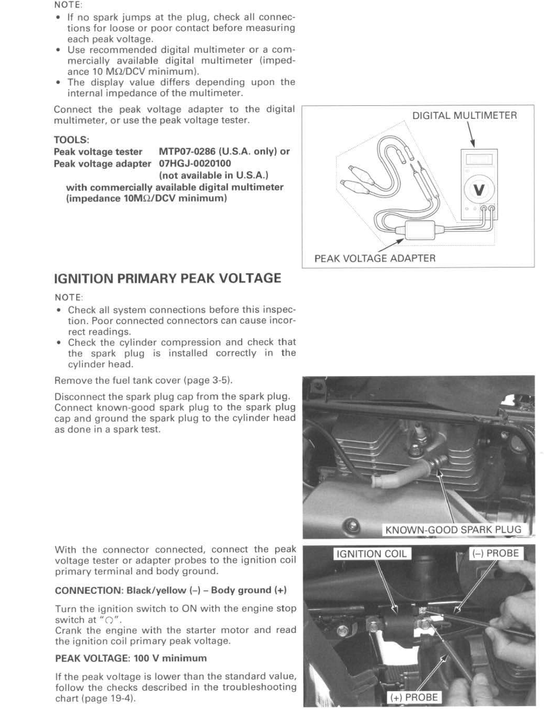
The ESI 530 should be trustworthy. What is the peak voltage of the CKP sensor measured at the ECU connector? What was the peak voltage at the ignition coil before it lost spark?
I've been too busy to chime in up to this point, but I'll try to check back here a couple times a day. Odds are we can fix it.
-
7 hours ago, rich250rracer said:This is one of the items Honda lists in the trouble shooting for no peak voltage at the coil.
So you aren't getting any peak voltage at the Black/yellow coil wire?

Try reversing the polarity of the Peak Voltage Adapter leads between Black/yellow and ground on the coil (positive PVA lead on Black/yellow, negative PVA lead on ground) and see if you get any peak voltage?
Your multimeter should be dialed to DC volts mode, since the PVA uses a diode to capture 1/2 waves of the CKP sensor AC sine wave voltage and stores those 1/2 waves (now rectified DC rather than AC voltage) in a capacitor inside the PVA.
-
So.... what I'm saying is your gear position switch is fine, else the neutral light would not light up on the display and the starter would not work when you press the starter button.
Your no spark issue is a head scratcher for sure!
-
6 hours ago, rich250rracer said:While I kind of grasp what you are saying here, forgive me if I seem skeptical. The reason for that is while the green/red wire in the harness for the gear position switch loses ground when I turn the key on, BOTH of the green ground wires at the ECU do NOT.
If I'm following you right, the two green wires in the ECU connector are direct to frame grounds, so no voltage is possible on those unless/until the ECU is plugged in and key is on. You can measure the DC volts present on those two green ECU wires after unbolting them from the frame but that's not advised because ECUs are expensive, delicate & fragile gizmos. Seems like they can fry if ya just cuss at them one too many times.....
While the Green/red neutral switch to ground wire completes the circuit for the neutral light and the N indicator on the dash, as well as provides the ECU with a neutral gear signal and on most Hondas completes the circuit for the starter solenoid, so the voltage present that overwhelms the multimeter resistance mode is being provided by the dash display. If there were no voltage on the Green/red (in neutral with the key on) the neutral light would not have lit up in your video. You can find out how many volts are on that Green/red gear position switch wire by unplugging the switch and probing from the Green/red to ground in DC volts mode, with the key on.
Multimeters cannot handle voltage while in any resistance or continuity modes. If voltage is sufficient the meter will fry while in resistance mode. That's a well known fact... That's why multimeter instructions always remind the user to use AC volts mode on high range when probing an unknown circuit. Then drop to DC volts mode to insure that no voltage is present before resuming testing in other modes.
EDIT: Just to add info on why multimeters cannot function in modes other than Volts or Amps in live circuits, the battery in the multimeter is used to provide voltage for measuring resistance, capacitance, inductance etc. modes in a closed circuit to the probes. If your meter has a 9 volt battery in it then it sends 9 volts through the measuring probes.... if it has two 1.5 volt batteries in it then it sends 3 volts through the measuring probes.
One or two 1.5 volt batteries powering multimeters are becoming more common nowadays - because many modern sensitive electronic chips will fry if they receive more than 1.5v or oftentimes more than 3 volts while being measured - 9 volt meters are obsolete. If you introduce external voltage while measuring you can fry stuff.... the multimeter as well....
-
In case this is useful.... a member recently measured a new OEM ignition coil (2010 420 Rancher) and provided us with the specs. I think your model uses the same part number... Resistance between the two primary winding terminals on the coil should measure around 2.75 ohms. Between each primary terminal and the end of the spark plug cable should measure around 18500 ohms (18.50K ohms). Between each primary terminal and ground (the stack of metal plates on the end of the coil is ground) and between the end of the spark plug cable and ground should all measure open circuit.
If the coil measures close to those specs try running a jumper wire from the positive battery post to the Red/Black terminal on the coil with the coil still plugged into the harness. See if you get spark.
You may have to recheck the peak voltages on the CKP and at the coil, make sure that one of them haven't failed since you first tested them.
The ignition switch is a suspect in my mind. I've seen them fail intermittently and under load, opening the ignition like yours was doing after a few minutes of runtime.
-
1 hour ago, jeepwm69 said:The gear position switch tests good when in neutral. The reason why the multimeter fails to measure continuity (resistance actually) when the ignition switch is turned on is because multimeters cannot function in resistance modes while there is voltage present. Resistance & continuity tests must be performed with the ignition switch off, or the battery disconnected (or the circuit under test unplugged/isolated from voltage).
-
I've never seen a bad TPS kill spark either, but it should be replaced if it's bad to rule out that possibility.
-
Yeah good reading, so the green/yellow is not shorted to ground which likely means that the ECM is bad. However, there is no way to test the ECM so the decision whether to replace it or not is all yours.
-
3 hours ago, jeepwm69 said:I’m just glad it’s fixed.
Me too! Glad ya had the cojones to make the call on the ECM 'cause I wasn't gonna.
-
Measurements look more trustworthy now. On your green to plug wire boot and black to plug wire boot, does your autoranging meter display 18.50K ohms? The range indication may appear in the corner of the screen where you may not notice it......
Also FYI just in case, the stack of metal plates sticking out of the end of the coil is ground for measurement purposes.
With the 33p ECM connector unplugged and the green/yellow unplugged from the coil, check continuity or resistance again between the green/yellow coil harness wire terminal and ground. The result should be an open circuit.
-
I'm not saying your guides are bad... your 450 is low miles and if you've replaced valves before you won't need a machine shop. Likely just replace the valve seals and lap the valves in and run it.
-
-
6 minutes ago, Igetby said:what kind of damage would it cause riding it like that? If its a guide or the seat..
No point in riding it, just tear it down and fix it. Who knows, it might have been sunk... just gonna do more damage running it.
-
Well, epoxy melts at 450-550 degrees F, depending on the resin type so whenever those desperado days come around I'll be firing my WWII (mfg 1945) Tappan Deluxe!
-
I worked on a 450 once that had a loose valve guide (they're pressed into the aluminum head) that had risen up out of the head far enough that the underside of the valve spring retainer was hitting the top of the valve guide each time the intake valve opened, but the noise was intermittent and seemed to hammer more often when the motor was revved up. I fixed it by pulling the valve guide out of the head, cleaned up the guide and it's bore with 91% alcohol, then coated the guide and it's bore with Red Loctite and pushed the guide back in place. After cleaning up the excess Loctite I let it harden overnight then lapped that valve in to the seat with lapping compound and it's still running strong. You'll never know what you'll find wrong until ya open it up!
Do you know how many hours/miles are on your 450?
-
4 hours ago, jeepwm69 said:have any of you opened up one of these newer ECU’s? I’m just curious if we get 20 years down the road if these things will all end up as junk due to a lack of availability, especially on oddball models like the 12-13 Foreman
I haven't opened one yet. I haven't even worked on any of the 420s or 500s that had a bad ECM yet. I'm just guessing but, those ECMs are probably potted in resin (like the old CDIs, Fan Control and Shift ECM modules are) which could mean they could be a bugger for desperados to repair.
-
Wow very nice machines! I envy you!
-
1
-
-
The experts have got your back! The only thing I can add is: do not EVER replace ANY part with a china knockoff. Buy genuine OEM Honda parts only, or else!
I like Vince at Mr Crankshaft too, the Vesrah rods and his work are top notch.
-
I need a few days (very busy right now) to build a Peak Voltage Adapter for you. I'll PM you when I get one ready to ship.
-
12 minutes ago, Mach 1 said:Oh, one more thing..isn't thats what fuses are for? I would think if I turn key, it would blow ignition fuse before it would allow coil to fry? Kinda like initial issue when I turn key would immediately blow fuse. Hard to wrap my head around now fuse good, but no spark?? Gonna order new coil, just leery of getting coil from same company may have gotten a bad one. Will update with new coil.
We don't know enough about how the ECM controls the coil so we must assume that a good coil may possibly get hot over time without blowing a fuse. Just don't plug the next new coil in until we learn more about it.
Order your next coil from RockyMountainATV beginning at this link to insure that you get a genuine Honda coil (part number 30510-HP5-601) :
2011 TRX500FPM no spark when hot.
in Electronics
Posted
@rich250rracer, my laptop went down and I am now limping along on my backup/spare laptop. So until I get a new laptop up and running and get my data copied over I'll be out.... hopefully someone can help ya in the meantime. As for my situation it's gonna be a long haul, likely a month or longer. Wish ya the best!