
retro
-
Content Count
4,007 -
Joined
-
Last visited
-
Days Won
70
Posts posted by retro
-
-
3 hours ago, Wheeler said:& polish plastics,
What do you use to polish your plastics? Do you use a buffer wheel on them?
-
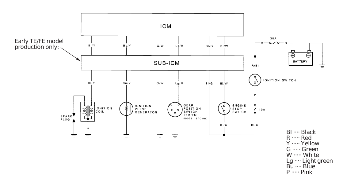
Coil voltage should be 12.5+ volts with the key on, so the battery might be too low/dead. I'd charge it up or jump it with a good battery and try again. The CKP (pulse gen) tests should go like so:

-
It's been a good while eh? 5 years ago I think....
-
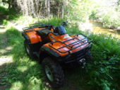
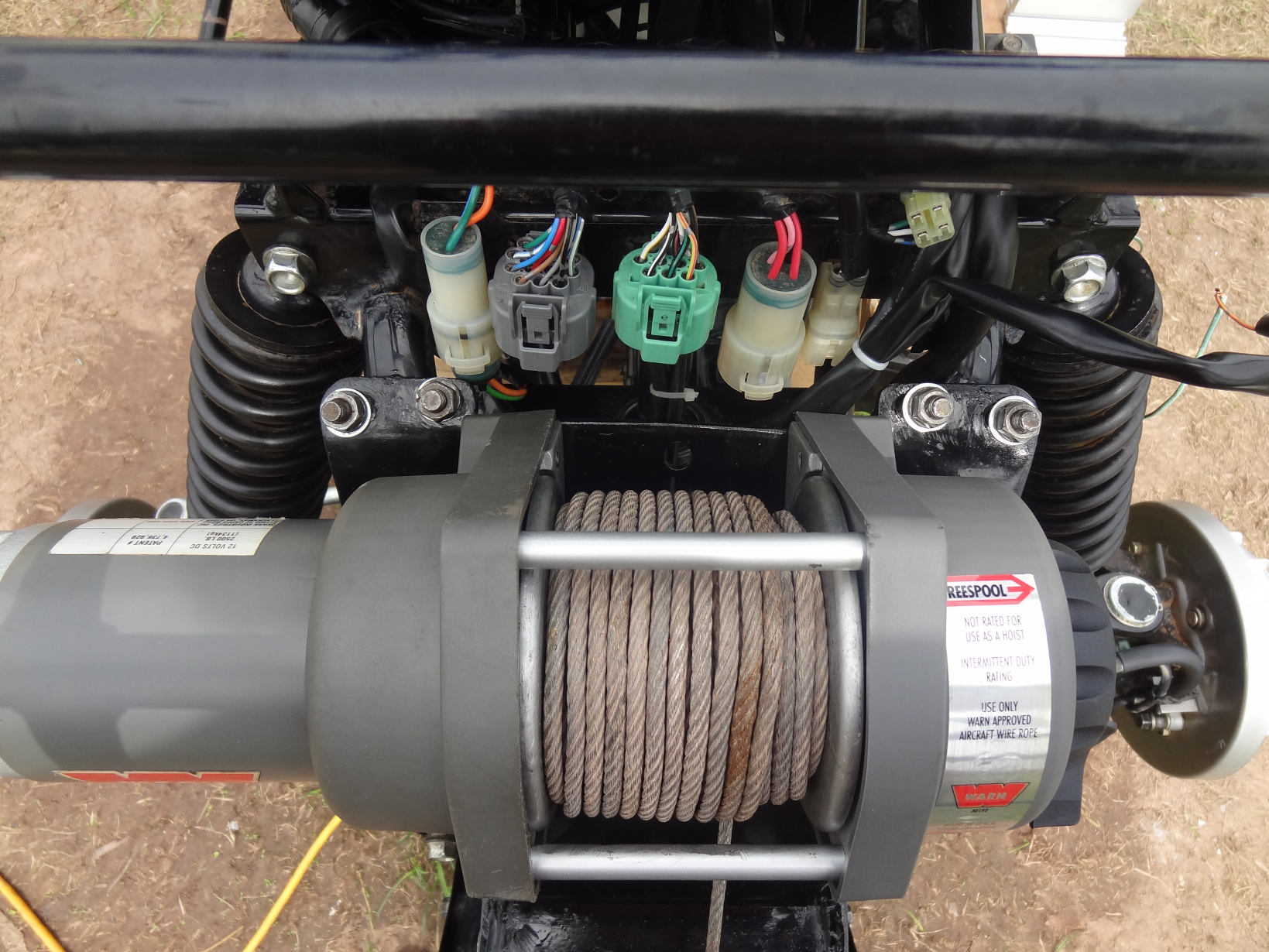
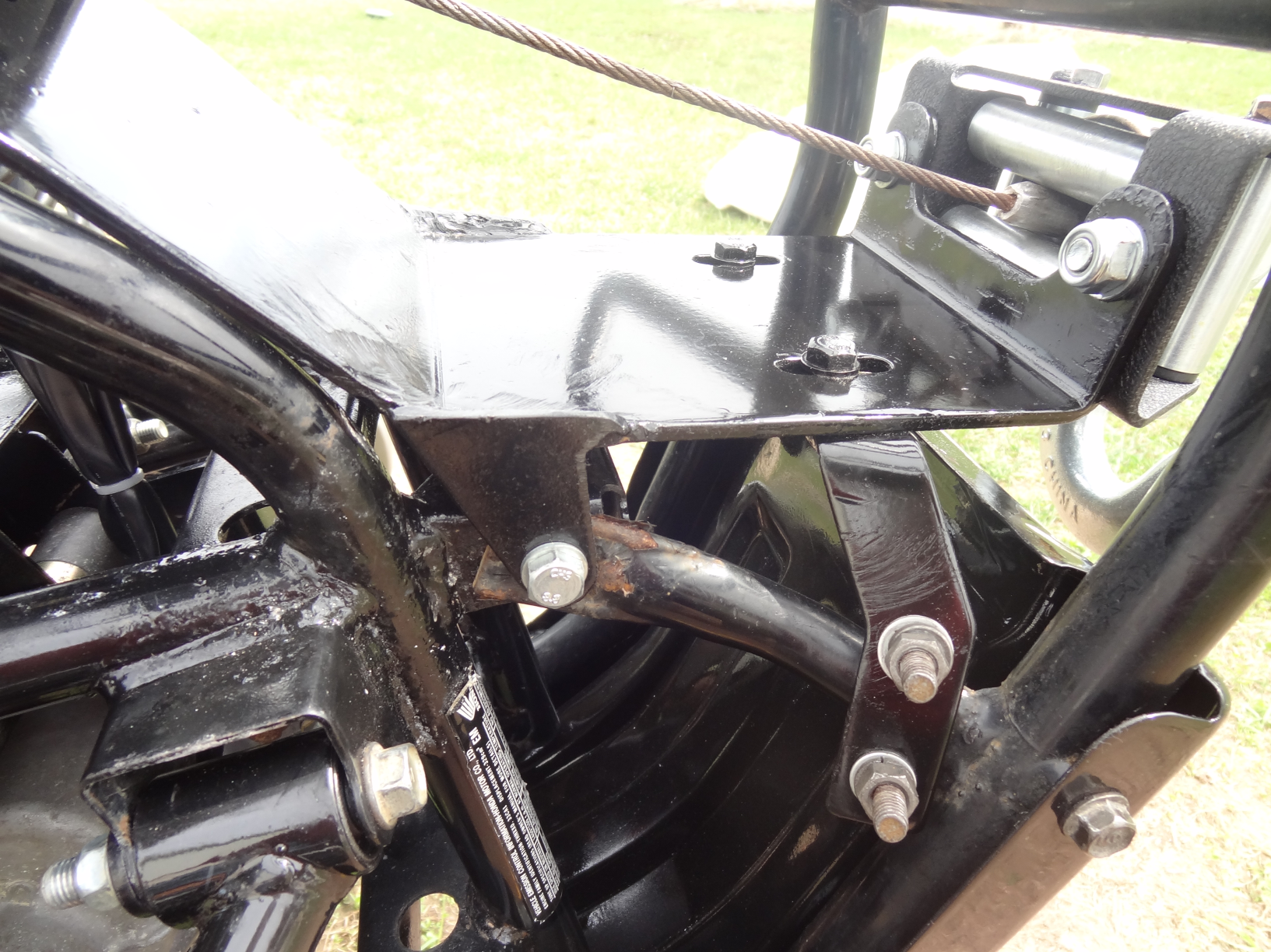
I put a KFI mount on my '00 Rancher that Jeepwm69 gave me. I didn't have any issue with the fit of the roller fairlead. I did cut the two side bolt brackets off of it and relocated them with my welder though, so I could slide the mounting plate up the frame tubes as high as possible. Here's pics of the finished mount.
-
 1
1
-
-
Poor grounds can cause intermittent loss of Ignition so I'd remove and clean up all of those before trying a regulator/rectifier swap. There is the negative battery cable where it bolts to the motor, a ground cable between the motor and the frame and a wiring harness bundle to frame ground. All of them are bolted down so they're easy to shine up once ya get plastics out of the way.
-
OK, thanks for the info! The Black/White wire terminal inside the CDI connector should have positive battery voltage while the Ignition switch is turned on and the Start/Stop switch is in the Run position. The Green/White wire terminal inside the CDI connector should be frame ground. So if you do not measure any DC volts between the Black/White and Green/White terminals while the ignition key is on and the kill switch is in the Run position then it's most likely a faulty handlebar Start/Stop switch. Since your handlebar Switches Assembly is a china fake then an OEM Honda replacement part should fix it. That is.... assuming that there are no blown fuses in the fuse box.
Fake china parts are garbage. They never work for more than a few minutes, and rarely ever work even for a second. China fakes fry other expensive parts often so don't ever buy that garbage again.... Let us know how it runs tomorrow after you swap on the genuine Honda switches. And Welcome to ATVHonda!
-
1
-
-
Tell us what you are working on, year & model. What is the issue? Have any parts been replaced? Are all parts on the ATV genuine Honda parts? Is the wiring harnesses in good condition with no splices, rodent damage or other damage?
-
Is the battery healthy? Does the starter crank the motor over at normal speed?
What is the full model number and the country (USA, Canada, UK, Australia, Sweden) of origin?
-
On 1/29/2024 at 2:23 PM, PeterV said:I had to replace the carburetor and the spark plug, changed out the oil and it seems to run fine for a while, but then it just will not start.
Did you replace the carb with OEM? Aftermarket (china knockoffs) parts do not work on Honda ATVs.
-
4 hours ago, jeepwm69 said:So I feel like you idiot/ Jeep proofed this thing….lol
What does the button on the end do?
Aye nah... it's not quite jeep proof'd, it just did not come with any instructions, haha!
The button is a momentary switch. It's function and purpose is to drain captured peak voltage from the storage capacitor inside after every test.... it resets the voltage measurement to 0 volts DC so you can repeat PV tests immediately and repeatedly.... rather than wait for the capacitor to drain on it's own.
Just make sure that you disconnect one of the PVA leads from the Ignition coil before you depress the reset button, because the coil has battery voltage across it while the Ignition switch is turned on... if you press the reset button while battery voltage is present you might (or might not) let all of the magic smoke out of it, depending on whether I took that sort of usage case into consideration when I put the PVA together? I don't remember.... so to be safe disconnect the lead from the coil before pushing the button. There is no initial battery voltage present across the Crank position/Pulse generator so you can leave the leads connected while resetting for another test in those cases.
By the way, all credits belong to @Melatv, that homemade PVA was made to match his DIY circuit that he posted either here, or possibly on the old VS forum? If I put it together right it should work great.
EDIT: Here are the links to @Melatv's DIY PVA threads:
https://www.hondaatvforums.net/threads/make-your-own-test-adapters.120450/
https://www.hondaatvforums.net/threads/peak-voltage-adapter.34406/
-
 1
1
-
-
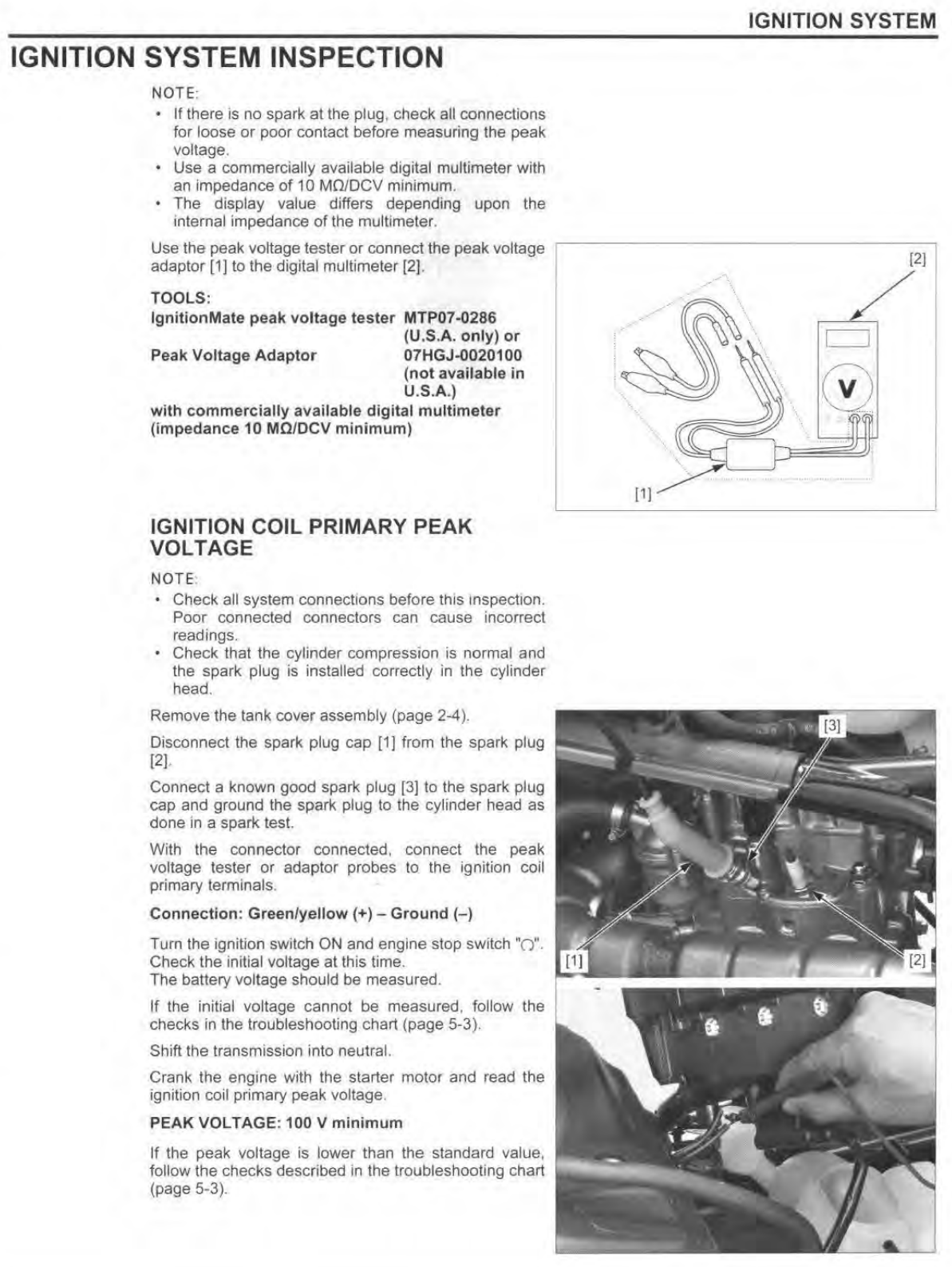
Yeah the PCM/ECM controls the coil and it's a good thing that I looked in the manual because I was thinking it worked differently than what the manual says. Anyway, since you have initial battery voltage at the coil, I think a Peak Voltage test is the next logical thing to do. If I remember right I sent you a homemade PVA a few years ago.... do ya still got that lil' bugger stashed away somewhere? There are two leads coming out of each end (total of 4 leads - they may have alligator clips on them) of the homemade PVA, with one end labelled "to Meter" or something to that effect. If you can find it try this with your multimeter set on DC Volts mode:
If you don't get a measurement on the first attempt try reversing the PVA leads where they attach to the Green/Yellow and ground, just in case PVA polarity is backwards...
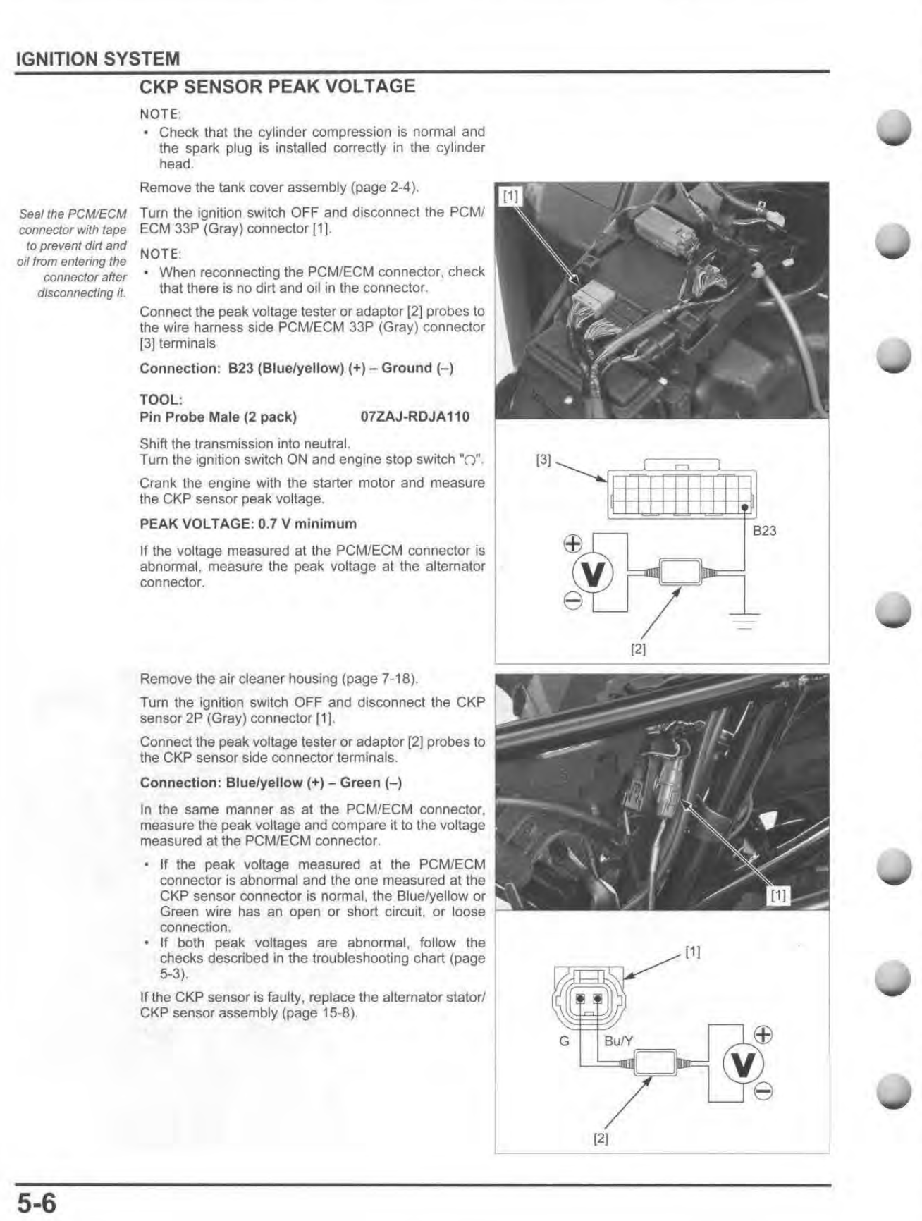
If you still don't measure any pulses perform the same test on the CKP/Pulse gen:
-
7 hours ago, jeepwm69 said:someone "went after the mayor with a gun"
I'm a results-centered guy.... doesn't move the needle for me....

-
 2
2
-
-
Which year is your TRX250? Sounds like the float valve and float seat in the carburetor need attention. Helps to know what ya got before advising on a repair though.
-
There are several grounds... there is a ground cable between the motor and the frame too, held down to the frame with a bolt. There is also a wiring harness ground bolt. All of them may need to be removed and shined up.
-
Try turning the screw clockwise a couple turns first, then turn it counter-clockwise until you feel a slight resistance. As Jeep said it helps to clean the threads up by turning the screw in and out a few times so it turns easily enough that you'll feel that initial resistance point. You may have to lubricate the threads if it doesn't turn easily.
-
Y'all plumb just like I do. Hahah....
-
Smarter than the average Bear, eh Booboo!!!
Neighboring businesses and households gonna be eyeballin' and taking pictures of your stuff now, I imagine. Pity the fools who have no men with skills working for them.... yet!

-
1
-
-
27 minutes ago, Flywheel said:Joined to see if I can get my display fixed. Thx
Welcome both of you! Paging @AKATV....
-
1
-
-
You'll need a '04-'07 400AT front differential (preferably complete with the three sub-harnesses and plastic clutch cover) and a '04-'07 400AT front driveshaft. It is a bolt-in swap (you'll have to notch for diff clearance in the frame as shown in Jeep's guide), the only other parts you'll need are a 400AT/Rincon/Foreman throttle assembly with a selectable switch and sub-harness, which you'll swap your stock Rancher throttle assy. top cover onto. If you convert your Rancher post it up for us!
-
This is not gambling advice, just sayin'.....
Y'all knew that nothing is ever left to chance, right....? Just asking for a friend..... who thinks that we oughta bankrupt the criminal gambling industry this weekend. I ain't a player though. Besides, there are four teams remaining, this lil' "slip" might have been intentional. Know what I'm sayin'....
-
2
-
-
Awesome! Thanks for sharing! Have fun, hope you hang around.
-
Make a mental note where each bearing come from so you can put them back. Then you reinstall each of the bearings by gently tapping them down into their bores while keeping them straight. You can use the end of a plastic screwdriver handle to tap them down until each one is flush with the bottom of the narrow 45 degree chamfer that is machined into the top of each bearing bore. The key thing here is to drive the bearings in straight. If any one of them is cocked sideways in a bore even just a tiny bit, the reduction gear will bind against and rub against the cover which will cause excessive friction and a no-shift issue. Keep us posted on your ES prep.
-
1
-
-
You can put the cover in a pot of water and bring the water to a boil. Then fish the cover out of the hot water and rap it sharply on a piece of soft wood or something soft. Those bearings will all fall out of the cover..... then you can push the broken gear stub out of the bearing.
Wear gloves when handling the hot cover and attach a short piece of wire to the cover before you dip it, so you'll be able to pull the cover out of the hot water without risking a burn.
Immediately after the bearings cool down lay them down on a flat, clean surface and force synthetic bearing grease into each bearing until they are fully packed using your finger to push grease past the metal shields. The metal shields have a narrow gap in them where they will accept grease. Packing them with grease immediately will force all of the water out of the bearings and prevent them from immediately beginning to rust. So have your synthetic grease ready....
Congrats on finding the problem! Stay warm!
-
When the change clutch is properly adjusted there should be 1/4 turn of the adjusting screw counterclockwise, where initial resistance is felt. The initial resistance that you'll feel is the adjusting screw making contact with the clutch release hardware. If you were to continue to turn the screw against resistance you would be releasing the clutch with the screw which is a bad thing to do - you would be making the clutch slip. If you were to back out the screw from the initial resistance more than 1/4 turn clockwise you would be providing too much slack in the release mechanism - in that case the clutch may not fully release during shifts which may cause shifts to fail. So it is imperative that you only allow 1/4 turn of slack in the adjusting screw for proper clutch operation. Turn the screw in and out a few times to get a feel for finding the first contact of the screw against the change mechanism.... you should be able to feel the screw making contact without forcing it at all. Then back it out 1/4 turn exactly, hold the screw still while you tighten the locknut down.
Put some grease on the threads of the screw and locknut to prevent those threads from rusting and seizing up.


No spark, 2013 500 Foreman ES (now not fixed again)
in Electronics
Posted
Correct that.... coil voltage should be 12.5+ battery voltage on the Black/Red wire terminal. The voltage on the Yellow/Green terminal of the coil will be less than battery voltage due to resistance in the windings of the coil. So your 10+ volts at rest measurement may be normal...? Anyway, if there is no measured voltage peaks over 100 volts DC between the Yellow/Green and frame ground then the pulse generator/ckp tests are due up next.